 English
 Français
 Español
 عربى
عربىIndustry News
Home / News / Industry News / Miniature Circuit Breaker Construction: Key Components, Working & Types


Content
Imagine a wiring fault in a final distribution circuit. The prospective short-circuit current can rise to 6 kA or more in under 10 ms, and the miniature circuit breaker (MCB) has only a few milliseconds to interrupt it. Whether the breaker succeeds comes down to one thing: how it is built.
The construction of an MCB is a deliberately engineered sequence of mechanical and thermal events. A typical MCB contains a molded insulating housing, a set of contacts, a bimetallic strip for overload protection, a solenoid for short-circuit protection, an arc chute, and connecting terminals. Understand how those parts are constructed and arranged, and you can predict how the breaker will behave under fault conditions, and why selection mistakes happen.
The short answer is this: the bimetallic strip gives the MCB its delayed inverse-time response to overloads, while the solenoid gives it an instantaneous response to short circuits; the arc chute then determines whether the breaker clears a high-current fault cleanly or fails at its rated breaking capacity.
Although MCBs vary by manufacturer and rating, the physical building blocks are consistent across the industry. Each subassembly handles a distinct phase of protection.
The housing is molded from a thermoset insulating material, usually a flame-retardant resin that stays rigid even when the internal temperature rises during tripping. It provides mechanical strength, electrical insulation, and protection against accidental contact with live parts. The terminals at the line and load ends are typically screw or cage-clamp type, rated for the conductor sizes the breaker can accept. The housing also guides the tripping toggle and carries the electrical ratings printed on the front face.
The heart of the breaker is a pair of contacts, one fixed and one moving, made from a silver-based alloy. They carry the load current in the closed position and must resist welding when a fault occurs. The moving contact is linked to a spring-loaded mechanism that stores energy; when the latch is released, that energy forces the contacts apart very quickly regardless of how slowly the user moves the toggle. Contact opening speed, contact pressure, and contact material quality are the main factors separating a reliable breaker from one that damages its own contacts after a few trips.
The thermal trip uses a bimetallic strip, two bonded metals with different coefficients of thermal expansion. Load current passes through the strip, or through a small heater around it, and when the current exceeds the rated value long enough, the strip bends and releases the latch. This creates the familiar inverse-time characteristic: a modest overload takes minutes to trip, while a heavy overload trips in seconds. Calibration of this strip, and its consistency from unit to unit, determines whether the breaker protects the cable without nuisance trips.
For short circuits, thermal response is far too slow. The magnetic trip consists of a solenoid coil carrying the line current and a spring-loaded plunger. When fault current surges through the coil, the magnetic field pulls the plunger and trips the mechanism almost instantly, typically within a few milliseconds. The pickup threshold of the solenoid defines the breaker type: B, C, or D, depending on how many times the rated current is required to trigger it.
When the contacts separate under load, an arc forms between them. The arc chute, usually a stack of de-ion plates inside a molded chamber, splits the arc into smaller arcs, cools it, and increases its voltage until the arc cannot sustain itself. Within the compact width of an MCB, the geometry of this chute is the limiting factor for breaking capacity. This is why two breakers with the same current rating can have very different kA ratings: the better the arc-extinguishing design, the higher the short-circuit current the breaker can interrupt safely.
With those components in mind, the operating sequence becomes easy to follow.
Suppose a circuit draws 20 percent more current than its rating. The bimetallic strip warms slowly, bends, and after a delay that depends on the magnitude of the overload, releases the latch. The longer the overload lasts, or the higher its value, the shorter the delay. This delay is intentional: it lets harmless inrush currents, such as motor starting or capacitor charging, pass without tripping.
When a real short circuit occurs, current jumps to many times the rated value. The solenoid sees the surge and pulls the plunger immediately, bypassing the thermal strip entirely. The result is a fast interruption that limits the energy and let-through current delivered to the faulted circuit.
After the fault is cleared, the bimetallic strip cools and the solenoid plunger returns to its rest position. The MCB is reset by moving the toggle to the off position first, then back to on. If the fault persists, the breaker trips again, using the same mechanical construction repeatedly, provided the fault current stayed within its rated breaking capacity.
Selection starts with rated current and breaking capacity, then moves to the tripping curve, which is a direct consequence of the magnetic trip setting.
| Type | Instantaneous trip range | Typical applications |
|---|---|---|
| Type B | 3 to 5 times rated current | Resistive loads, lighting, socket outlets in domestic and commercial wiring |
| Type C | 5 to 10 times rated current | Small motors, transformers, lighting with large inrush, most industrial circuits |
| Type D | 10 to 20 times rated current | Transformers, welding equipment, motors with very high inrush current |
The rated breaking capacity (Icn, typically 4.5 kA to 10 kA for residential MCBs tested to IEC 60898-1) is the maximum short-circuit current the device can clear without damage. Installing an MCB with inadequate breaking capacity where the prospective fault current is high is a safety problem, not just a performance issue.
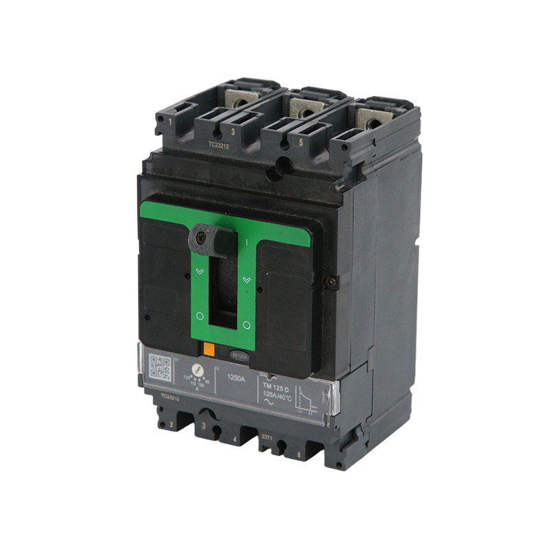
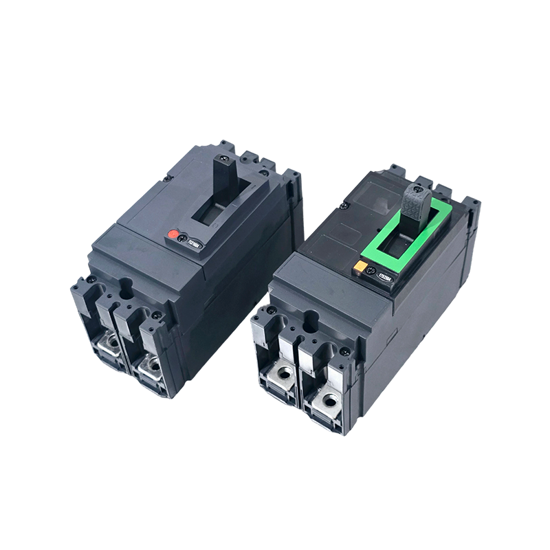
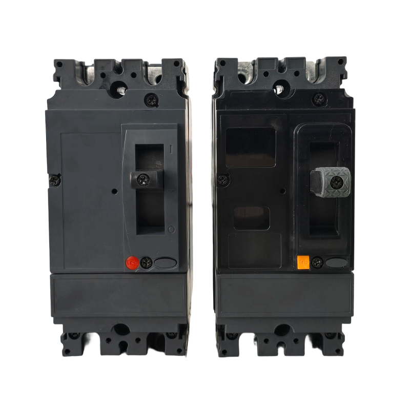
When the distribution point demands more than an MCB can offer, the same thermal-magnetic construction scales up into a molded case circuit breaker. For these situations our EZC series MCCB, covering 100 A to 1600 A, is a natural next step for low-voltage distribution.
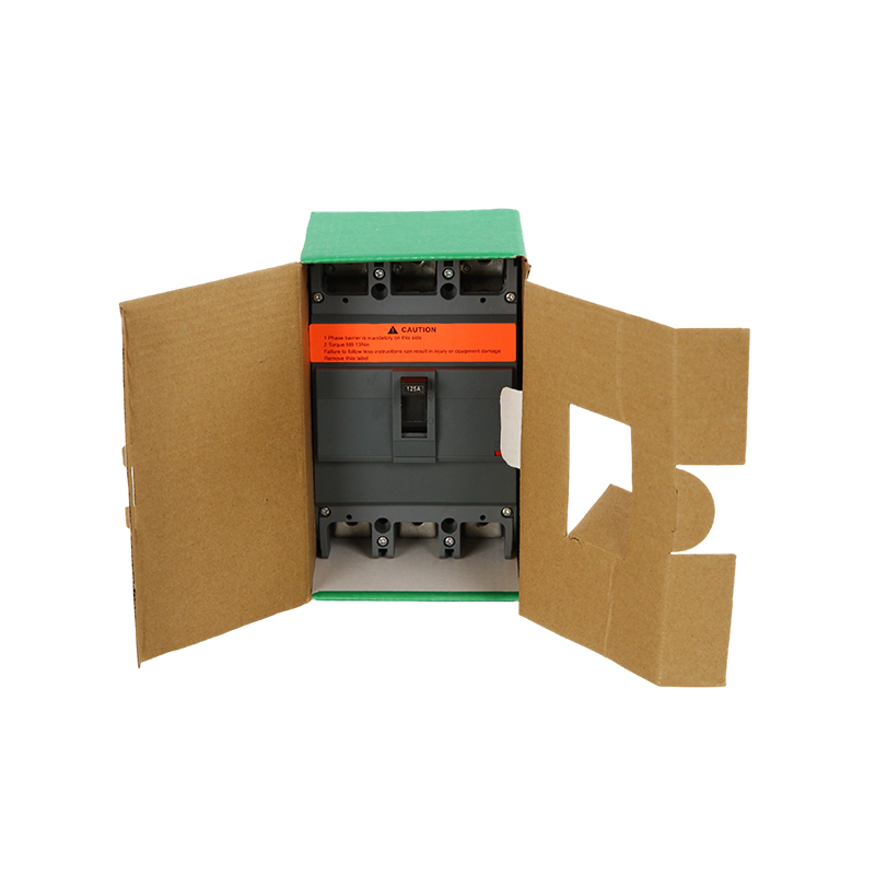 EZC Molded Case Circuit Breaker 100A–1600A for Low-Voltage Power Distribution SuMingtuo, China Wholesale EZC Molded Case Circuit Breaker 100A–1600A for Low-Voltage Power Distribution Suppliers and EZC Molded Case Circ...View Product →
Seen from the factory floor, MCB construction is a study in consistency. A thermal trip that is calibrated correctly on paper will still misbehave if the bimetal strip varies between batches. Contact material quality, molding precision, and trip mechanism alignment decide whether a breaker passes type tests and delivers the same performance in every unit.
This is why we build our breakers around a full production chain, from part processing to final assembly, and why our manufacturing and quality-control setup emphasizes stable processes. Being based in Liushi, where the complete electrical supply chain is concentrated, gives us direct control over raw materials and quick feedback from production.
Where precision timing is critical, a digital electronic trip adds another layer. The MTM1E digital electronic MCCB, rated at 125 A with a 50 kA breaking capacity, replaces the bimetallic adjustment with microprocessor-controlled protection, giving closer coordination with downstream MCBs.
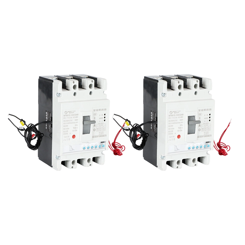 MT-M1 Digital Electronic MCCB, 100-800A, 3/4P, 50kA, Microprocessor-Controlled CMingtuo, China Wholesale MT-M1 Digital Electronic MCCB, 100-800A, 3/4P, 50kA, Microprocessor-Controlled Circuit Breaker Suppliers and MT-...View Product →
Application-specific construction also matters. A solar PV array protects DC circuits, where current does not pass through a natural zero and arcs behave differently than in AC. For such installations, a PV DC MCCB rated at 1000 V and 630 A for solar applications uses the contact and arc-chute construction needed to interrupt DC current reliably.
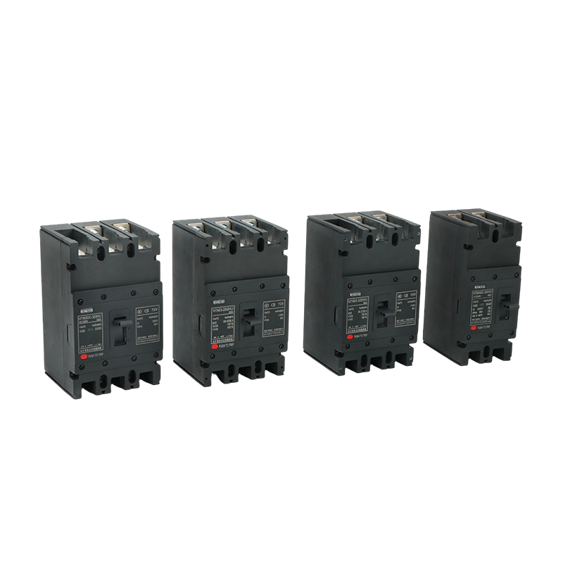 Solar PV DC MCCB Suppliers, DC MCCB in Solar Photovoltaic SystemsMingtuo-DC Molded Case Circuit Breakers Suppliers and Solar PV DC MCCB Factory in China, offer Wholesale PV DC MCCB 1000V 630A Solar Circ...View Product →
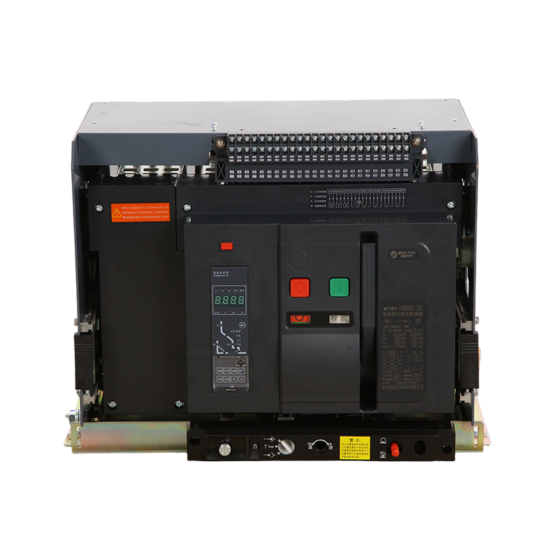
At the largest end of the distribution hierarchy, main incomers are often protected by air circuit breakers rather than MCBs; you can compare that different construction in our air circuit breaker guide.
MCB construction is not a black box. The bimetallic strip and solenoid provide the two protection responses, the arc chute defines the breaking limit, and the housing, contacts, and terminals determine durability. When you look at a breaker, you are looking at those few subassemblies working together.
For everyday circuits, a correctly selected Type B or C MCB is dependable protection. When fault levels rise, or when coordination and precision matter, the same principles scale up into MCCBs and electronic trip units. Start with the construction, match it to the circuit conditions, and the selection becomes straightforward.
Zhejiang Mingtuo Electrical Technology Co., Ltd. All Rights Reserved.
Electrical Protection Circuit Breakers Medium Voltage Circuit Breakers Manufacturers Low Voltage Circuit Breakers Factory
