 English
 Français
 Español
 عربى
عربى
Air Circuit Breakers: How They Work, Types and Selection Guide
Content
- 1 How Air Circuit Breakers Work
- 2 Air Circuit Breaker vs Other Low-Voltage Breaker Types
- 3 Trip Unit Functions and Protection Settings
- 4 Selective Coordination with Air Circuit Breakers
- 5 Draw-Out vs Fixed Mounting
- 6 Typical Applications by Industry
- 7 Key Ratings and Standards to Check Before Specifying
- 8 Maintenance Intervals and Contact Wear Indicators
- 9 Zone-Selective Interlocking for Faster Fault Clearance
- 10 Common Sizing Mistakes and How to Avoid Them
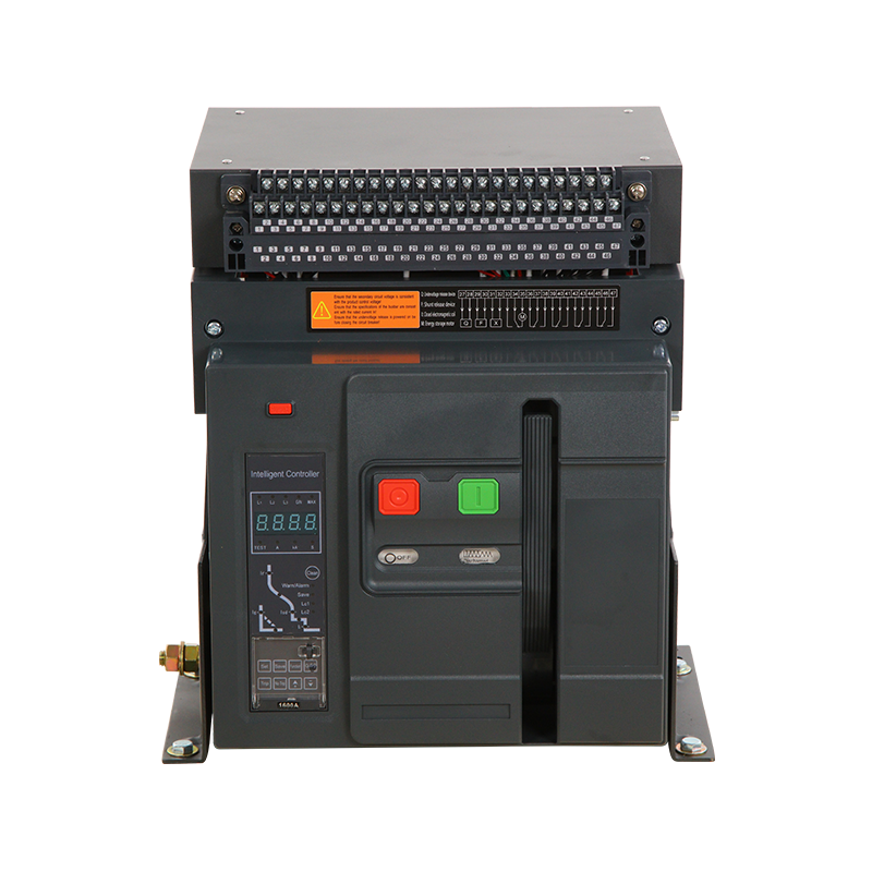
Air circuit breakers are automatic switching devices that interrupt fault currents in low-voltage electrical systems using air as the arc-extinguishing medium. They are the preferred choice for high-current applications in industrial and commercial power distribution, typically rated from 630A up to 6300A or more, where reliable fault protection and operational flexibility are essential. Unlike molded case circuit breakers, air circuit breakers offer advanced trip unit configurations, draw-out mounting, and in-service maintenance capabilities that make them indispensable in main switchboards and bus coupler positions.
How Air Circuit Breakers Work
When a fault or overload occurs, the trip unit signals the operating mechanism to separate the contacts. The resulting arc between the contacts is drawn into an arc chute assembly, where it is divided into smaller arcs by a series of metal splitter plates. This process rapidly increases the arc voltage until it exceeds the system voltage, extinguishing the arc within milliseconds.
The entire interruption happens in open air, which is why these devices are called air circuit breakers. Modern units can interrupt fault currents of 85 kA or higher at 690V AC, making them suitable for the most demanding low-voltage distribution environments.
Key Components Inside an Air Circuit Breaker
- Main contacts and arcing contacts that separate under fault conditions
- Arc chute with deion plates or magnetic blowout coils for arc extinction
- Stored-energy spring operating mechanism for consistent opening and closing speed
- Electronic or electronic-relay-based trip unit for overload and short-circuit detection
- Draw-out carriage for safe isolation and maintenance without de-energizing the busbar
Air Circuit Breaker vs Other Low-Voltage Breaker Types
Understanding where an air circuit breaker fits relative to other technologies helps engineers select the right device for each position in the distribution system.
| Feature | Air Circuit Breaker | Molded Case Circuit Breaker | Miniature Circuit Breaker |
|---|---|---|---|
| Typical current range | 630A to 6300A+ | 16A to 1600A | Up to 125A |
| Mounting type | Fixed or draw-out | Fixed or plug-in | DIN rail |
| Trip unit type | Fully programmable electronic | Thermal-magnetic or electronic | Thermal-magnetic fixed |
| In-service maintenance | Yes, draw-out allows contact inspection | Limited | No |
| Communication capability | Modbus, Profibus, Ethernet IP | Optional | Rarely |
For a 2000A incoming feeder in a large data center or manufacturing plant, an air circuit breaker is almost always the correct selection. For a 250A sub-distribution board feeding lighting circuits, a molded case circuit breaker is more appropriate and economical.
Trip Unit Functions and Protection Settings
The trip unit is the intelligence of an air circuit breaker. Modern electronic trip units combine up to seven independent protection functions in a single programmable module, giving engineers precise control over system selectivity and fault discrimination.
Standard Protection Functions
- Long-time (L): Overload protection with an adjustable current pickup (typically 0.4 to 1.0 times rated current) and inverse-time delay to allow motor starting surges.
- Short-time (S): Delayed short-circuit protection used to achieve selective coordination with downstream devices. Delay bands range from 100ms to 500ms.
- Instantaneous (I): Undelayed trip for very high fault currents, protecting the busbar and cabling from thermal and mechanical damage within one half-cycle.
- Ground fault (G): Detects leakage current to earth, protecting equipment and personnel. Pickup is typically set at 20% to 100% of rated current.
- Neutral protection (N): Ensures the neutral conductor is protected proportionally in four-pole configurations.
Advanced Metering and Alarm Functions
Higher-specification trip units go beyond protection. They measure real-time current per phase, voltage, power factor, energy consumption, and harmonic distortion. Some units log trip events with timestamps and fault current magnitudes, enabling root-cause analysis after a fault. This data can be transmitted to a building management system or SCADA platform via digital communication protocols such as Modbus RTU or IEC 61850.
Selective Coordination with Air Circuit Breakers
Selective coordination means that only the protective device immediately upstream of a fault operates, leaving the rest of the system energized. Achieving full selectivity in a tiered distribution system is one of the primary reasons engineers specify air circuit breakers at the top of the protection hierarchy.
Consider a three-level system: an incoming air circuit breaker at 4000A, sub-distribution air circuit breakers at 1600A, and molded case circuit breakers at 400A. By setting the 4000A unit with a 400ms short-time delay, the 1600A units with a 200ms delay, and the 400A units with a 100ms delay or instantaneous trip, a fault on a final circuit will be cleared by the 400A device without disturbing the 1600A or 4000A levels. This is current-time selectivity in practice.
For this approach to work, each air circuit breaker must have a short-time withstand current rating equal to or greater than the prospective fault current at its location. Ratings of 50 kA for 200ms or 85 kA for 100ms are common specifications for main distribution boards fed from large transformers.
Draw-Out vs Fixed Mounting
Air circuit breakers are available in two fundamental mounting configurations, each with distinct operational advantages.
Draw-Out (Withdrawable) Configuration
The breaker is mounted on a carriage with three positions: connected, test, and disconnected. In the test position, control circuits remain energized but main power contacts are isolated. This allows relay testing and functional checks without de-energizing the upstream busbar. In the disconnected position, the unit can be physically removed from the cubicle for contact inspection or replacement. Draw-out mounting is standard practice for incoming breakers feeding critical loads where downtime is unacceptable.
Fixed Configuration
The breaker is bolted directly to the switchboard busbars. This arrangement is simpler and more compact but requires the upstream supply to be isolated before any maintenance work can begin. Fixed mounting is acceptable for outgoing feeders with lower criticality or in applications where capital cost reduction is a priority.
Typical Applications by Industry
Air circuit breakers appear in virtually every sector that relies on high-current low-voltage distribution. Below are common use cases with the specific requirements that drive their selection.
Data Centers
Main incoming breakers at the low-voltage switchboard downstream of a 2000 kVA or larger transformer commonly operate at 3200A to 4000A. Draw-out mounting and full selective coordination are mandatory. Energy metering through the trip unit supports power usage effectiveness reporting.
Industrial Manufacturing
Motor control centers and machine tool distribution boards use air circuit breakers at the incomer position to protect against upstream faults and to provide a manual isolation point. A 1600A unit feeding a section of a production line, for example, must withstand repeated motor starting inrush currents of six to ten times full load without nuisance tripping, which the long-time pickup and delay settings accommodate precisely.
Hospitals and Healthcare Facilities
Continuity of power in critical care areas is a patient safety requirement. Air circuit breakers with zone-selective interlocking allow upstream and downstream devices to communicate directly. When a downstream breaker detects a fault, it signals the upstream air circuit breaker to delay its trip, ensuring the fault is cleared as close to the source as possible while maintaining supply to other sections of the board. This reduces unnecessary de-energization of life-safety circuits.
Renewable Energy and Utility Substations
Large-scale solar farms and wind turbine collector systems use air circuit breakers at the low-voltage output of inverter transformers. Four-pole versions protect both phase and neutral conductors, which is critical in transformer-isolated systems where neutral displacement can occur during earth faults.
Key Ratings and Standards to Check Before Specifying
Selecting an air circuit breaker requires verifying several rated values against system requirements. Overlooking any one of these can result in equipment damage or failure to interrupt a fault.
- Rated ultimate short-circuit breaking capacity (Icu): The maximum fault current the breaker can interrupt once. Must exceed the prospective short-circuit current at the installation point.
- Rated service short-circuit breaking capacity (Ics): The fault current the breaker can interrupt repeatedly. Typically expressed as a percentage of Icu, often 100% for air circuit breakers intended for repeated operation.
- Rated short-time withstand current (Icw): The fault current the breaker can carry for a defined period without tripping or damage, critical for selective coordination calculations.
- Rated voltage: Must match or exceed the nominal system voltage, commonly 400V, 415V, 440V, or 690V AC.
- Rated frequency: 50 Hz or 60 Hz; confirm if the installation is in a variable-frequency drive output circuit, where derating may apply.
- Applicable standards: IEC 60947-2 governs low-voltage circuit breakers and defines the test procedures for all the above ratings. Some markets also require UL 1066 compliance for air circuit breakers used in North American panels.
Maintenance Intervals and Contact Wear Indicators
Air circuit breakers require periodic maintenance to ensure reliable operation over a service life that can span 20 to 30 years. Most manufacturers recommend a maintenance inspection every 12 months or after a specified number of operating cycles, whichever comes first. Common maintenance ratings are 10,000 mechanical operations and 2,000 electrical operations at rated current.
What a Routine Maintenance Inspection Covers
- Visual inspection of main contacts for pitting, erosion, or carbon deposits; contact replacement when wear indicators reach the minimum thickness marked on the contact assembly
- Cleaning and lubrication of the operating mechanism and draw-out carriage rails with appropriate dielectric grease
- Testing the trip unit by primary injection or secondary injection to verify pickup and time-delay settings are within tolerance, typically plus or minus 10%
- Checking the arc chute for carbon accumulation and replacing deion plates if heavily eroded
- Torque verification on all busbar and cable terminations to prevent high-resistance joints that cause overheating
Infrared thermographic scanning during normal operation is a valuable supplementary technique. A temperature rise of more than 10 degrees Celsius above adjacent terminals of the same phase indicates a developing fault at a connection, allowing corrective action before a failure occurs.
Zone-Selective Interlocking for Faster Fault Clearance
Zone-selective interlocking, often abbreviated ZSI, is a hardwired communication scheme between air circuit breakers in the same distribution board or between a main breaker and its feeders. When a fault occurs, the breaker nearest the fault asserts a restraint signal to the upstream device. The upstream breaker, receiving the restraint signal, knows it is not the closest device to the fault and holds its short-time delay. The downstream breaker clears the fault at its fastest setting without waiting for the full delay. If the downstream breaker fails to clear the fault within a preset time window, typically 80ms to 100ms, the upstream breaker overrides the restraint and trips.
ZSI combines the speed of instantaneous tripping with the selectivity of time-delayed coordination, reducing arc flash energy at downstream panels while preserving supply continuity at the main board. This makes it particularly valuable in hospitals, semiconductor fabs, and other facilities where both safety and continuity are non-negotiable.
Common Sizing Mistakes and How to Avoid Them
Even experienced engineers occasionally make errors in air circuit breaker selection. The following are the most frequently encountered sizing issues.
Underestimating Prospective Short-Circuit Current
The prospective fault current at a main switchboard fed by a 2500 kVA transformer at 400V with 6% impedance is approximately 60 kA. Specifying a breaker with an Icu of only 50 kA would be a dangerous undersizing. Always calculate the maximum fault contribution including any connected generators or large capacitor banks.
Ignoring Derating for Ambient Temperature
Air circuit breakers are rated at 40 degrees Celsius ambient inside the enclosure. In outdoor switchrooms or tropical climates where enclosure temperatures regularly reach 55 degrees Celsius, the continuous current rating must be derated, typically by 8% to 12% depending on the model. Failing to apply this derating leads to accelerated contact wear and spurious long-time trips.
Selecting Fixed Mounting for Critical Feeders
Specifying a fixed-mount breaker to save costs on a critical incomer means that any maintenance or replacement requires a complete shutdown of the downstream distribution board. For a feeder serving a production line operating around the clock, the cost of one unplanned shutdown will far exceed the price difference between fixed and draw-out mounting.
Recommended Products


Zhejiang Mingtuo Electrical Technology Co., Ltd. All Rights Reserved.
Electrical Protection Circuit Breakers Medium Voltage Circuit Breakers Manufacturers Low Voltage Circuit Breakers Factory
