 English
 Français
 Español
 عربى
عربى
Circuit Breakers: LV, Medium Voltage & Electrical Protection Guide
Content
- 1 What Circuit Breakers Do and Why Choosing the Right One Matters
- 2 How Circuit Breakers Provide Electrical Protection: The Core Mechanism
- 3 Low Voltage Circuit Breakers: Types, Ratings, and Selection
- 4 Medium Voltage Circuit Breakers: Technologies and Applications
- 5 Electrical Protection Functions in Modern Circuit Breakers
- 6 Selectivity and Discrimination: Making the Right Breaker Trip
- 7 Key Selection Parameters for Circuit Breakers
- 8 Circuit Breaker Standards: IEC, ANSI, and What They Mean for Procurement
What Circuit Breakers Do and Why Choosing the Right One Matters
A circuit breaker is an automatic protective switching device that detects abnormal electrical conditions — overcurrent, short circuit, or earth fault — and interrupts current flow before equipment is damaged or personnel are endangered. Unlike a fuse, which must be replaced after operating, a circuit breaker resets and can be returned to service after the fault is cleared. This reusability, combined with precise adjustable protection settings, makes circuit breakers the primary electrical protection device in every voltage class from domestic 240 V installations to utility-scale 1,200 kV transmission systems.
The two categories most relevant to industrial and commercial electrical engineering are low voltage circuit breakers (LVCBs), operating at voltages up to 1,000 V AC or 1,500 V DC, and medium voltage circuit breakers (MVCBs), covering the range from 1 kV to approximately 52 kV. Each category encompasses distinct technologies, standards, and selection criteria. Getting the specification wrong — whether undersizing the breaking capacity or mismatching the protection characteristic to the load — creates safety hazards, nuisance tripping, or failure to clear genuine faults.
How Circuit Breakers Provide Electrical Protection: The Core Mechanism
All circuit breakers share the same fundamental operating sequence: detect an abnormal condition, initiate a trip, separate the contacts, extinguish the arc that forms as contacts open, and hold the open-circuit position until manually or automatically reset. The differences between breaker types lie in how each of these steps is performed.
Overcurrent Detection: Thermal, Magnetic, and Electronic
The trip unit is the sensing and decision-making element of the circuit breaker. Three technologies are used:
- Thermal-magnetic trip units (standard in molded case circuit breakers): A bimetallic strip heated by load current provides inverse-time overload protection — the higher the overload, the faster the trip. A magnetic solenoid provides instantaneous short-circuit protection by responding to the magnetic field of high fault currents, typically above 10–20× rated current. No external power required; entirely self-contained.
- Electronic trip units (ETUs) (standard in air circuit breakers and high-specification MCCBs): Current transformers measure load current continuously; a microprocessor evaluates the signal against programmed protection curves. ETUs provide fully adjustable long-time (overload), short-time (time-delayed short circuit), instantaneous (instantaneous short circuit), and ground-fault protection — the so-called LSIG protection functions. Settings are precise to ±5% accuracy, compared to ±20% for thermal-magnetic units.
- Microprocessor-based protection relays (medium voltage): Separate from the breaker mechanism itself, these relays measure current via external CTs and communicate trip commands to the breaker's trip coil over a control cable. Protection functions can be extremely sophisticated — differential, distance, directional overcurrent — and can be updated in firmware without replacing hardware.
Arc Interruption: Why It Differs by Voltage Class
When contacts separate under load, an arc forms that must be extinguished before interruption is complete. The arc energy increases with the square of the current and proportionally with voltage, so arc interruption at medium voltage is a fundamentally different engineering challenge than at low voltage. Low voltage breakers use arc chutes — a series of metal splitter plates that divide the arc into short segments, cooling and extinguishing it within the breaker housing. Medium voltage breakers use separate arc-interrupting media: vacuum, SF₆ gas, or (historically) oil and air blast. Vacuum interruption is now the dominant technology for medium voltage, achieving arc extinction in a single half-cycle (8–10 ms) through near-instantaneous condensation of metal vapor plasma in the 10⁻⁶ mbar vacuum environment.
Low Voltage Circuit Breakers: Types, Ratings, and Selection
Low voltage circuit breakers (governed by IEC 60947-2 in most markets and UL 489 in North America) are manufactured in four primary formats, each targeting a different current range and application context.
Miniature Circuit Breakers (MCBs)
MCBs are the smallest and most numerous circuit breaker type — billions are installed worldwide in residential and light commercial distribution boards. They are available in current ratings from 0.5 A to 125 A and breaking capacities typically from 6 kA to 25 kA (IEC 60898). Trip characteristics are standardized:
- Type B: Instantaneous trip at 3–5× In. Used for resistive loads and cable protection where inrush is absent.
- Type C: Instantaneous trip at 5–10× In. The most common type for general commercial and light industrial loads, tolerating moderate motor inrush.
- Type D: Instantaneous trip at 10–20× In. Specified for heavy inductive loads — transformers, large motors, welding equipment — where startup currents are very high.
Molded Case Circuit Breakers (MCCBs)
MCCBs cover the range from 16 A to 3,200 A with breaking capacities from 10 kA to 200 kA (Icu). The molded case — a glass-fiber reinforced thermoset housing — contains all components including the arc chute, trip mechanism, and terminals. MCCBs are the workhorse of industrial power distribution: motor control centers (MCCs), sub-distribution boards, and feeder protection.
A critical distinction in MCCB specification is between Icu (ultimate breaking capacity) and Ics (service breaking capacity). Icu is the maximum fault current the breaker can interrupt once, after which it may need to be replaced. Ics is the fault current the breaker can interrupt and remain fully serviceable — typically 50–100% of Icu. For installations where the breaker must reliably interrupt repeated faults, Ics must exceed the prospective fault current at the installation point.
Air Circuit Breakers (ACBs)
ACBs cover the highest current range in low voltage: 630 A to 6,300 A, with breaking capacities up to 150 kA at 415 V. They are the standard protection device for main incomer and bus-tie positions in large low-voltage main distribution boards (MDBs). All ACBs use electronic trip units with the full LSIG protection suite, and most modern units offer communication via Modbus, Profibus, or IEC 61850 protocols for integration with building management and energy monitoring systems. ACBs are draw-out (withdrawable) as standard, allowing safe replacement or maintenance while adjacent circuits remain energized.
Residual Current Circuit Breakers with Overcurrent Protection (RCBOs)
RCBOs combine MCB overcurrent protection with residual current (earth leakage) detection in a single device. The residual current element detects imbalance between live and neutral currents — indicating current flowing to earth via a fault or a person. Standard tripping thresholds are 30 mA for personal protection (trip time <40 ms at 5× I∆n) and 300 mA for fire protection. RCBOs are mandatory in circuits supplying socket outlets in most national wiring codes and are increasingly required for EV charging circuits.
| Type | Current Range | Max Breaking Capacity | Trip Unit | Typical Application |
|---|---|---|---|---|
| MCB | 0.5–125 A | 25 kA | Thermal-magnetic (fixed) | Residential, commercial final circuits |
| MCCB | 16–3,200 A | 200 kA | Thermal-magnetic or ETU | Industrial feeders, MCCs, sub-boards |
| ACB | 630–6,300 A | 150 kA | ETU (LSIG + comms) | Main incomers, bus-tie, large MDBs |
| RCBO | 6–125 A | 10–25 kA | Thermal-magnetic + RCD | Socket circuits, EV charging, bathrooms |
Medium Voltage Circuit Breakers: Technologies and Applications
Medium voltage circuit breakers (defined under IEC 62271-100) operate in the range of 3.6 kV to 52 kV, protecting power transformers, feeders, motors, capacitor banks, and bus sections in utility distribution networks and industrial power systems. At these voltages, arc interruption requires a dedicated arc-quenching medium — air alone is insufficient to reliably extinguish arcs within the physical dimensions of practical switchgear.
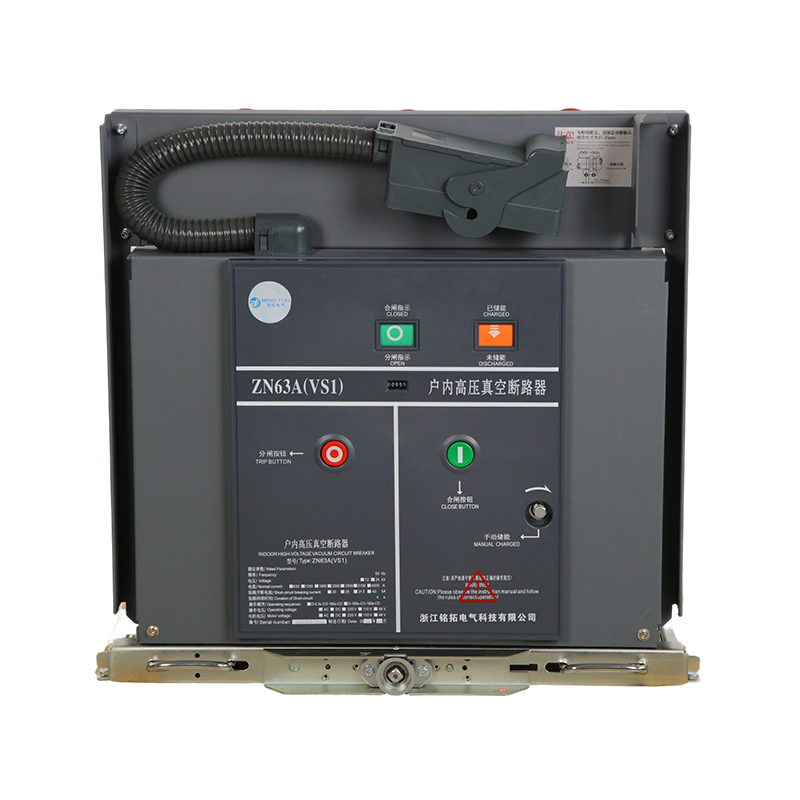
Vacuum Circuit Breakers (VCBs): The Industry Standard
VCBs dominate new medium-voltage installations worldwide. The vacuum interrupter — a sealed ceramic-metal bottle evacuated to 10⁻⁶ to 10⁻⁴ mbar — provides near-instantaneous arc extinction, exceptional electrical endurance (100 fault interruptions at rated short-circuit current), and a 10–20 year maintenance-free operating life. Contact erosion per interruption is measured in micrometers, and the sealed design means no arc-quenching medium is ever consumed or needs replenishment. VCBs are available in ratings from 3.6 kV to 40.5 kV, with short-circuit breaking currents from 16 kA to 50 kA and normal current ratings from 630 A to 4,000 A.
SF₆ Circuit Breakers: High Voltage Workhorse Under Regulatory Pressure
Sulfur hexafluoride (SF₆) gas has exceptional dielectric strength — approximately 2.5× that of air at equal pressure — and outstanding arc-quenching properties due to its high electronegativity. SF₆ breakers dominate high-voltage applications (72.5 kV and above) and remain in service at medium voltage in gas-insulated switchgear (GIS). However, SF₆ has a global warming potential of 23,500 times CO₂ over 100 years, and the EU's F-Gas Regulation (EU 2024/573) bans new medium-voltage SF₆ equipment in the EU from 2031, accelerating the industry's shift to vacuum and alternative-gas technologies.
Oil Circuit Breakers: Legacy Equipment Still in Service
Bulk oil and minimum oil circuit breakers were the standard medium-voltage protection technology before the 1990s. Oil both insulates and extinguishes the arc through vaporization and decomposition. Oil breakers are no longer manufactured for new installations but large numbers remain in service in aging distribution networks globally. Their principal liabilities are fire and explosion risk from oil, high maintenance requirements (oil sampling, filtering, and replacement every 1–3 years), and large physical size. Replacement with VCBs is standard practice during any significant substation refurbishment.
| Technology | Voltage Range | Maintenance Interval | Environmental Risk | Status |
|---|---|---|---|---|
| Vacuum (VCB) | 3.6–40.5 kV | 10–20 years | None | Dominant — new standard |
| SF₆ Gas | 3.6–1,200 kV | 5–10 years | GWP 23,500 (EU ban 2031) | Phase-out at MV; dominant at HV |
| Bulk / Min. Oil | 3.6–36 kV | 1–3 years | Fire / explosion risk | Legacy only — no new production |
| Air Blast | Up to 765 kV | 1–5 years | Noise pollution | Legacy only |
Electrical Protection Functions in Modern Circuit Breakers
The protection functions built into or associated with a circuit breaker define its ability to respond selectively and correctly to every type of abnormal condition in the electrical network. Modern electronic trip units and digital protection relays implement standardized protection functions designated by ANSI/IEEE device function numbers and IEC protection relay designations.
LSIG: The Standard Low Voltage Protection Suite
Electronic trip units in ACBs and high-specification MCCBs implement four protection functions, collectively known as LSIG:
- L — Long-Time (Overload): Inverse-time protection against sustained overcurrents above rated current. Adjustable threshold (Ir, typically 0.4–1.0× In) and time delay (tr). Protects conductors against thermal damage from sustained overload.
- S — Short-Time: Time-delayed protection for high overcurrents that are clearly faults but not quite instantaneous events. Provides selectivity — the downstream breaker trips before the upstream, limiting the outage to the affected circuit. Adjustable threshold (Isd, 2–15× In) and intentional delay (tsd, 0.1–0.5 s).
- I — Instantaneous: Non-delayed trip at very high fault currents (typically above 15× In). Protects against bolted short circuits close to the breaker where fault energy would be enormous even in 100 ms. Can be disabled on incomer ACBs where downstream selectivity is required.
- G — Ground Fault: Detection of residual current indicating earth fault. Can be set to operate at currents well below the phase overcurrent elements (typically 0.2–1.0× In), providing protection against high-impedance earth faults that would not be detected by overcurrent elements alone.
Medium Voltage Protection Functions
At medium voltage, protection is performed by separate numerical relays that send trip commands to the circuit breaker. Common protection functions applied to MV feeder and transformer protection include:
- ANSI 50/51 — Overcurrent (instantaneous / inverse-time): The fundamental feeder and equipment protection function. Standard time-current characteristics include IEC Normal Inverse (NI), Very Inverse (VI), and Extremely Inverse (EI), selectable to coordinate with downstream fuses and breakers.
- ANSI 50N/51N — Earth Fault: Residual current measurement detecting single-phase earth faults. On isolated or Petersen-coil earthed networks, sensitive earth fault elements (ANSI 64) can detect earth fault currents as low as 1–2 A.
- ANSI 87 — Differential Protection: Compares current entering and leaving a protected zone (transformer, busbar, or motor). Trips instantaneously for any internal fault — extremely fast (<30 ms) and immune to through-fault current. The highest-grade protection for expensive or critical equipment.
- ANSI 79 — Auto-Reclose: After a trip caused by a transient fault on an overhead line, the relay commands the circuit breaker to reclose after a defined dead time (typically 0.3–1 s for instantaneous reclose, 15–60 s for delayed reclose). Approximately 80% of overhead line faults are transient (caused by tree contact, birds, or lightning), making auto-reclose highly effective at minimizing sustained outages.
- ANSI 27/59 — Under/Overvoltage: Monitors bus voltage and trips if it falls below or rises above set thresholds — protecting sensitive loads and detecting islanding in distributed generation applications.
- ANSI 46 — Negative Sequence Overcurrent: Detects unbalanced loading or single phasing, protecting motors from the severe rotor heating caused by negative-sequence current components.
Selectivity and Discrimination: Making the Right Breaker Trip
Selectivity (or discrimination) is the ability of a protection system to isolate only the faulted circuit while all healthy circuits remain in service. Poor selectivity — where an upstream breaker trips unnecessarily when a downstream fault occurs — is one of the most common and costly protection system failures in industrial plants and commercial buildings.
Four methods are used to achieve selectivity between cascaded circuit breakers:
- Current selectivity (ampere discrimination): The upstream breaker's instantaneous trip threshold is set above the maximum fault current that can flow through the downstream breaker. Only achievable when the impedance between the two breakers is sufficient to create a meaningful current difference between near and far faults — often not the case on low-impedance busbars.
- Time selectivity (time-current discrimination): The upstream breaker's short-time protection has an intentional delay (tsd), giving the downstream breaker time to clear the fault first. A grading interval of at least 0.25–0.3 s is required between adjacent breakers. This is the most common method but requires that the upstream breaker withstand the fault current for the delay period — necessitating an adequate short-time withstand rating.
- Zone selectivity interlocking (ZSI): Communication between adjacent breakers via a hardwired restraint signal. A downstream breaker in fault sends a blocking signal to the upstream breaker, which then delays its own trip. If no blocking signal is received (fault is behind the upstream breaker), it trips immediately. ZSI achieves near-instantaneous upstream operation while maintaining selectivity — eliminating the energy let-through associated with time-delayed operation.
- Energy-based selectivity (back-up protection): Relies on current limitation — current-limiting MCCBs with extremely fast operating times (<5 ms) limit peak fault energy so severely that they clear the fault before the upstream breaker can respond, based purely on the physics of the devices rather than coordination settings.
Key Selection Parameters for Circuit Breakers
Specifying a circuit breaker requires confirming that every rating parameter meets or exceeds the demands of the installation. Failure to verify any single parameter can result in dangerous inadequacy.
| Parameter | What to Verify | Source of Data |
|---|---|---|
| Rated Voltage | Breaker rated voltage ≥ system voltage | Network single-line diagram |
| Rated Current | In ≥ maximum continuous load current (with derating for ambient temp) | Load schedule / demand calculation |
| Breaking Capacity (Icu/Isc) | Icu ≥ prospective fault current at installation point | Short-circuit analysis (IEC 60909) |
| Peak Withstand Current | Ipk ≥ peak asymmetrical fault current (typically 2.1–2.5× Ik) | Short-circuit analysis |
| Trip Characteristic | Time-current curve coordinates with upstream and downstream devices | Protection coordination study |
| Operating Environment | IP rating, altitude derating (>2,000 m), temperature derating | Site survey, IEC 60947-2 derating tables |
| Standards Compliance | IEC 60947-2 (LV), IEC 62271-100 (MV), or local equivalent | Third-party type test certificates |
Altitude deserves specific attention: at elevations above 2,000 m, air density decreases, reducing both the dielectric strength of air and the cooling capacity for thermally-rated components. IEC 60947-2 requires derating of voltage rating by approximately 1.5% per 100 m above 2,000 m. A 415 V-rated MCCB installed at 3,500 m elevation must be derated to approximately 395 V effective rating — often requiring the next higher voltage class to be specified.
Circuit Breaker Standards: IEC, ANSI, and What They Mean for Procurement
The applicable standard determines the rating method, test requirements, and marking obligations for a circuit breaker. Mixing IEC-rated and ANSI-rated equipment in the same switchboard requires careful verification that ratings are genuinely equivalent — the two systems use different test methodologies that produce non-interchangeable numbers.
- IEC 60947-2: Low voltage circuit breakers (up to 1,000 V AC). The primary standard for European, Asian, Middle Eastern, and African markets. Defines Icu (ultimate breaking capacity), Ics (service breaking capacity), utilization categories (A and B for selectivity), and electrical endurance requirements.
- IEC 60898-1: MCBs for household and similar installations (up to 125 A, 440 V). Simpler standard than IEC 60947-2 with fewer adjustment options — appropriate for final circuit protection only.
- UL 489: North American standard for molded case circuit breakers. Uses different test sequences and power factors than IEC 60947-2, producing AIC (ampere interrupting capacity) ratings that are not directly equivalent to Icu. A UL 489 device with 65 kAIC rating has passed a different test than an IEC device with 65 kA Icu.
- IEC 62271-100: AC circuit breakers above 1 kV. The global medium-voltage standard, defining all rating parameters including rated voltage, normal current, short-circuit breaking current, TRV (transient recovery voltage) requirements, operating sequences, and mechanical endurance classes (M1: 10,000 operations; M2: 30,000 operations).
- ANSI/IEEE C37.04 and C37.09: North American medium-voltage circuit breaker standards. Use a different rated voltage and MVA-based rating system. Modern North American equipment is increasingly dual-rated to both IEC and ANSI.
For any safety-critical or high-value installation, always require third-party type test certificates from an accredited laboratory (such as KEMA, CESI, DNV, or UL) confirming that the specific breaker model has been tested to the claimed standard and rating. Manufacturer self-declaration without independent test evidence is insufficient for utility, industrial, or data center applications where protection failure would have serious safety or financial consequences.
Recommended Products


Zhejiang Mingtuo Electrical Technology Co., Ltd. All Rights Reserved.
Electrical Protection Circuit Breakers Medium Voltage Circuit Breakers Manufacturers Low Voltage Circuit Breakers Factory
