 English
 Français
 Español
 عربى
عربىIndustry News
Home / News / Industry News / How Do Vacuum Circuit Breakers Work and Why Are They the Industry Standard for Medium Voltage Protection?

Content
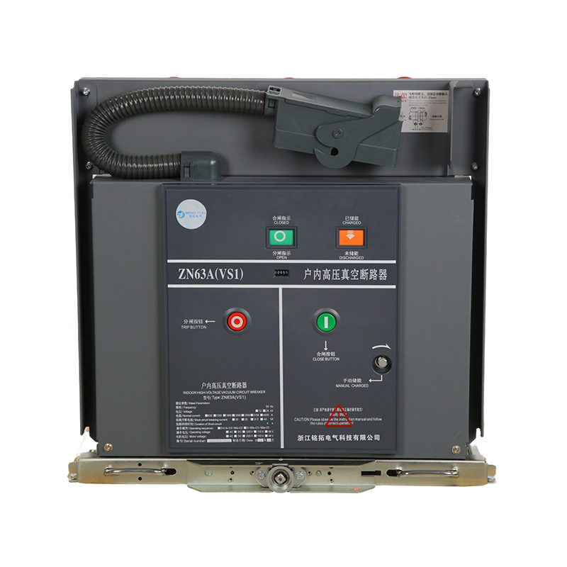
A vacuum circuit breaker (VCB) is a switching and protection device used primarily in medium voltage electrical distribution systems — typically in the range of 1kV to 38kV — that interrupts fault currents and isolates electrical circuits by extinguishing the arc formed between its contacts inside a sealed vacuum interrupter. The fundamental operating principle relies on the exceptional dielectric strength of a high vacuum (pressure below 10⁻⁴ mbar), which is approximately 8 to 10 times greater than air at atmospheric pressure. When the breaker's contacts separate under fault or switching conditions, an arc forms between them due to the vaporization of contact material. In the vacuum environment, this metal vapor arc has no supporting medium to sustain it — the vapor condenses rapidly on the surrounding metal shield within the interrupter, and the arc extinguishes cleanly at the first natural current zero crossing. The entire interruption process typically takes less than half a cycle of the power frequency.
The vacuum interrupter is the heart of the VCB — a hermetically sealed ceramic or glass-to-metal envelope containing a pair of contacts, a metallic arc shield, and a bellows assembly that allows the moving contact to travel the small contact gap (typically 8 to 12 mm for medium voltage applications) needed for interruption. Because the interrupter is a completely sealed unit, it requires no maintenance of the interrupting medium, never needs refilling or topping up, and is unaffected by atmospheric conditions, moisture, altitude, or pollution. This sealed design is one of the most significant practical advantages of vacuum technology over older oil or air blast circuit breakers, which required periodic maintenance of their interrupting media and were sensitive to contamination.
Vacuum circuit breakers have displaced oil circuit breakers, air blast breakers, and SF₆ breakers in the medium voltage market over the past four decades for a combination of technical, operational, and environmental reasons. Understanding these advantages helps engineers and asset managers make well-informed decisions when specifying protection equipment for new installations or replacement programs.
A complete vacuum circuit breaker assembly consists of several integrated subsystems, each of which must perform reliably for the breaker to fulfill its protection function. Understanding these components helps maintenance engineers diagnose problems and specify inspection procedures correctly.
The interrupter contains the fixed contact, the moving contact connected to a flexible bellows assembly, and a metal vapor condensation shield surrounding the contact gap. Contact materials are engineered alloys — typically copper-chromium (CuCr) for general medium voltage applications — chosen to provide good electrical conductivity, resistance to welding under short circuit currents, and controlled arc behavior that promotes rapid deionization. The ceramic-to-metal or glass-to-metal seals that form the hermetic envelope must maintain vacuum integrity over the full service life of the interrupter, typically 25 to 30 years. Vacuum integrity is verified periodically using a high-potential withstand test or a vacuum quality monitoring device.
The operating mechanism drives the moving contact between the open and closed positions with the force and speed required for reliable closing and interruption. Three mechanism types dominate modern VCB designs: spring-stored energy mechanisms (where coiled springs are charged by a motor or manually and released to operate the breaker), electromagnetic mechanisms (using a magnetic actuator directly driven by a capacitor discharge), and permanent magnet actuator (PMA) mechanisms that use the attraction and repulsion of permanent magnets to latch the breaker in both positions. Spring mechanisms are the most widely used and provide reliable operation independent of supply voltage fluctuation. Magnetic and PMA mechanisms offer very fast operating times and require less mechanical maintenance but depend on adequate capacitor energy storage.
The poles of the vacuum interrupter and the live parts of the breaker are insulated from ground and from each other by a combination of solid insulation — epoxy resin encapsulation of the interrupter and current-carrying components is standard in solid-insulated switchgear — and air gap insulation in open-type breaker designs. The insulation system must maintain its dielectric integrity under the rated power frequency voltage, lightning impulse voltage (BIL), and switching surge voltage for the full service life of the equipment in the expected environmental conditions.
Vacuum circuit breakers are specified according to a set of standardized electrical ratings that define their capability to operate safely and reliably within defined system conditions. These ratings are established by IEC 62271-100 (the primary international standard for AC circuit breakers above 1kV), IEEE C37.04, and equivalent national standards. The following table summarizes the most important rating parameters and their typical ranges for medium voltage VCBs.
| Rating Parameter | Typical Range | Significance |
| Rated voltage (Ur) | 3.6 kV – 40.5 kV | Maximum system voltage the breaker can withstand |
| Rated normal current (Ir) | 630 A – 4000 A | Continuous current without exceeding temperature limits |
| Rated short-circuit breaking current (Isc) | 16 kA – 63 kA | Maximum fault current the breaker can interrupt |
| Rated short-time withstand current (Ik) | 16 kA – 63 kA for 1–3 seconds | Fault current the breaker can carry without damage |
| Power frequency withstand voltage | 20 kV – 95 kV (rms, 1 min) | Dielectric strength of insulation system |
| Lightning impulse withstand (BIL) | 60 kV – 200 kV peak | Resistance to transient overvoltages from lightning |
| Mechanical operating life | 10,000 – 30,000 operations | Total switching operations before mechanism overhaul |
When selecting a VCB for a specific application, the rated short-circuit breaking current must exceed the maximum prospective fault current at the point of installation, calculated from the system impedance at that location. Specifying a breaker with insufficient interrupting rating — even marginally — is a serious safety failure: a breaker that cannot interrupt a fault it encounters will experience catastrophic mechanical failure and may cause an arc flash incident. Apply a margin of at least 10–20% above the calculated prospective fault current when selecting the breaker rating.
Vacuum circuit breakers are the dominant switching and protection technology in medium voltage distribution networks across virtually every industry sector that operates at distribution voltages. Their combination of reliability, low maintenance, and safety characteristics makes them the preferred choice in environments ranging from urban utility substations to remote industrial facilities.
One of the most commercially significant attributes of vacuum circuit breakers is their low maintenance requirement compared to older technologies, but "low maintenance" does not mean "no maintenance." A structured inspection and testing program is essential to verify that the breaker remains fit for service and to identify deterioration before it results in a failure to interrupt a fault — the most dangerous possible failure mode for a circuit breaker.
At intervals defined by the manufacturer's maintenance schedule — typically every 1 to 3 years or at defined numbers of operations — the breaker should be inspected for signs of external damage, contamination of insulating surfaces, corrosion of terminals and hardware, and correct function of auxiliary switches and interlocks. The operating mechanism should be exercised through several close-open cycles and the closing and opening times verified against the manufacturer's specified limits using an appropriate timing instrument. Mechanism lubrication points should be serviced according to the schedule, using only the lubricant types specified by the manufacturer — incorrect lubricants can damage seals or migrate onto insulating surfaces.
The vacuum integrity of the interrupter must be verified periodically because a gradual leak — imperceptible without testing — will allow the vacuum to degrade to the point where the interrupter can no longer interrupt fault current reliably. Two testing methods are used in the field: the high-voltage withstand test, in which a voltage well above normal operating voltage (but below the impulse withstand level) is applied across the open contacts and the absence of discharge or sparkover confirms adequate vacuum; and vacuum quality monitors, electronic instruments that detect the characteristic magnetic deflection of charged particles in the interrupter that occurs only when vacuum pressure has degraded above a threshold value. Both methods are described in IEC 62271-100 and manufacturer maintenance manuals.
Each fault interruption operation erodes a small amount of material from the contact faces, gradually reducing the contact travel to the closed position. Most VCBs incorporate a contact wear indicator — a mechanical gauge or mark on the operating linkage that shows the remaining contact travel — which allows maintenance personnel to verify that the contacts have not reached the end-of-life erosion limit without disassembling the interrupter. When the contact travel reaches the wear limit, the interrupter must be replaced, as operating beyond the wear limit reduces the vacuum gap to below the value required for reliable fault interruption.
Correct VCB selection requires a systematic evaluation of the electrical system parameters, the operational duty of the breaker, the installation environment, and the applicable standards. The following checklist covers the most critical selection parameters that must be determined before specifying a vacuum circuit breaker.
Vacuum circuit breakers have established their position as the technology of choice for medium voltage protection and switching through a combination of demonstrable performance advantages, safety benefits, and lifecycle cost economics that competing technologies cannot match across the full breadth of medium voltage applications. Specifying the correct rating, mechanism type, and special duty capability for each installation — and maintaining the equipment according to a structured, manufacturer-aligned maintenance program — ensures that the breaker delivers the protection reliability and service life that the investment represents.


Zhejiang Mingtuo Electrical Technology Co., Ltd. All Rights Reserved.
Electrical Protection Circuit Breakers Medium Voltage Circuit Breakers Manufacturers Low Voltage Circuit Breakers Factory
