 English
 Français
 Español
 عربى
عربى
What Are Air Circuit Breakers and How Do You Choose the Right One?
Content
- 1 What an Air Circuit Breaker Is and How It Works
- 2 Key Components Inside an Air Circuit Breaker
- 3 Types of Air Circuit Breakers and Their Installation Configurations
- 4 Understanding ACB Ratings: Current, Voltage, and Breaking Capacity
- 5 Protection Functions Provided by the Electronic Trip Unit
- 6 How to Select the Right Air Circuit Breaker for Your System
What an Air Circuit Breaker Is and How It Works
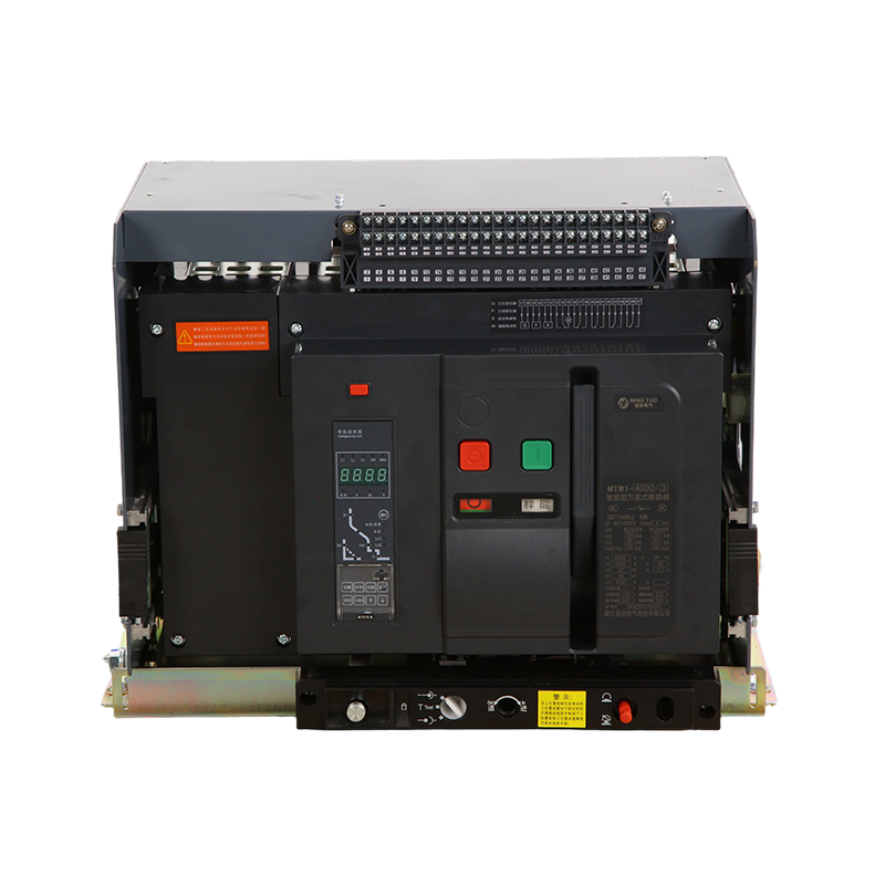
An air circuit breaker (ACB) is a type of electrical protection device designed to carry, switch, and protect electrical circuits against overloads, short circuits, and earth faults in low-voltage power distribution systems — typically those operating at voltages up to 1000V AC or 1500V DC. Unlike moulded case circuit breakers (MCCBs), which are sealed units with limited adjustability, ACBs are open-frame devices built for high-current applications ranging from 630A to 6300A, offering a comprehensive range of adjustable protective functions and the ability to be serviced and maintained in the field without replacement.
The operating principle of an air circuit breaker relies on air as the arc-extinguishing medium. When the breaker trips under fault conditions, its contacts separate and an electric arc forms between them. The ACB's arc chute — a series of metal plates arranged to divide, cool, and extinguish the arc — quenches this arc rapidly by lengthening it, increasing its voltage drop, and dissipating its thermal energy until current flow ceases. This arc interruption in air distinguishes ACBs from vacuum circuit breakers (which interrupt arcs in a vacuum interrupter) and SF₆ breakers (which use sulphur hexafluoride gas), making ACBs the preferred technology for accessible, maintainable, low-voltage main distribution applications.
Modern air circuit breakers are equipped with an electronic trip unit (ETU) — a microprocessor-based protective relay built into the breaker — that continuously monitors current on all phases and neutral and executes tripping decisions based on precisely programmed protection curves. The ETU replaces the older thermal-magnetic trip mechanisms with digital accuracy, offering time-current curves that can be adjusted without replacing components, real-time current measurement and logging, and communication interfaces for integration into building management and SCADA systems.
Key Components Inside an Air Circuit Breaker
Understanding the internal architecture of an ACB helps engineers specify, commission, and maintain these devices correctly. The major functional assemblies within a typical air circuit breaker are:
- Main contacts: Silver-alloy or copper-tungsten contact tips that carry full load current continuously. The contact geometry is designed to withstand the electrodynamic forces generated by high short-circuit currents without welding or excessive erosion.
- Arcing contacts: A separate set of contacts that make before and break after the main contacts, ensuring that arc erosion occurs on sacrificial arcing tips rather than the main current-carrying surfaces. This design significantly extends the operational life of the breaker.
- Arc chute assembly: Deion plates — typically steel or copper alloy — arranged in a stack above each contact pair. The arc is driven into the chute by magnetic blowout forces, divided into multiple shorter arcs in series, rapidly cooled, and extinguished. Arc chute design is the primary determinant of the ACB's breaking capacity.
- Operating mechanism: A stored-energy spring mechanism that charges either manually or via an electric motor, then releases energy instantaneously to open or close the contacts. The stored-energy design ensures contact separation speed is independent of operator effort or control voltage, providing consistent arc interruption performance.
- Electronic trip unit (ETU): The digital protection module housing current transformers, signal processing circuitry, and programmable protection functions. ETUs in modern ACBs measure true RMS current, detect harmonic-laden waveforms accurately, and provide long-time, short-time, instantaneous, and ground fault protection as standard, with optional earth leakage, zone selective interlocking (ZSI), and arc flash detection modules.
- Drawout mechanism (on withdrawable types): A racking assembly that allows the ACB to be withdrawn from its cradle to isolated, test, or removed positions without de-energising the busbar, enabling live maintenance and testing of the breaker without shutting down the distribution board.
Types of Air Circuit Breakers and Their Installation Configurations
Air circuit breakers are available in two primary installation configurations — fixed and withdrawable — each suited to different operational and maintenance requirements.
Fixed Air Circuit Breakers
Fixed ACBs are bolted directly to the switchboard busbars and cannot be removed from their mounting position without de-energising and disconnecting the power supply. They are the lower-cost option and are appropriate for installations where the breaker is unlikely to require frequent maintenance or replacement, or where the supply can be shut down for servicing without significant operational impact. Fixed ACBs are commonly used as main incomer breakers in smaller industrial and commercial installations and as outgoing feeders in medium-complexity distribution boards.
Withdrawable (Drawout) Air Circuit Breakers
Withdrawable ACBs are mounted in a cradle that connects to the busbars via isolating contacts. The breaker can be racked out to an isolated position — disconnecting it from the busbars while leaving the busbar energised — or fully removed from the panel for inspection, testing, or replacement. This configuration is essential for critical power infrastructure where continuity of supply is paramount, including hospital main distributions, data centre power systems, industrial process plants, and utility substations. The ability to perform routine maintenance, test the trip unit, and replace the breaker without a supply interruption provides significant operational advantages that justify the higher capital cost of the withdrawable design.
Horizontal and Vertical Mounting Orientations
Most ACBs are designed for horizontal mounting with current flow from bottom to top (standard orientation), but vertical mounting variants are available for installations where panel space constraints require the breaker to be positioned differently. It is critical to specify and install ACBs in the orientation for which they are rated — mounting an ACB upside down or at an unspecified angle alters the arc chute's ability to drive the arc upward into the deion plates, potentially reducing breaking capacity and increasing arc duration.
Understanding ACB Ratings: Current, Voltage, and Breaking Capacity
Correctly interpreting and applying ACB ratings is fundamental to safe and compliant installation. The following table summarises the key rating parameters and their practical significance:
| Rating Parameter | Symbol | Typical Values | Practical Meaning |
|---|---|---|---|
| Rated current | In | 630A – 6300A | Maximum continuous current the ACB carries without exceeding temperature limits |
| Rated voltage | Ue | Up to 1000V AC | Maximum system voltage the ACB is designed to operate at |
| Ultimate breaking capacity | Icu | 42kA – 150kA | Maximum short-circuit current the ACB can interrupt (once, without guarantee of continued service) |
| Service breaking capacity | Ics | 75–100% of Icu | Short-circuit current the ACB can interrupt and remain serviceable for continued use |
| Short-time withstand current | Icw | 42kA – 100kA for 1s | Maximum fault current the ACB can carry for a defined time without tripping (for ZSI coordination) |
The short-time withstand current (Icw) is a particularly important rating for main incomer ACBs in systems using zone selective interlocking. In a ZSI scheme, the incomer ACB intentionally delays its trip response to allow a downstream feeder ACB to clear a fault first, keeping more of the distribution system live. This delay means the incomer must withstand the full fault current for the duration of the downstream device's tripping time — typically 100–400 milliseconds — without being damaged. ACBs with high Icw ratings are therefore essential for discrimination in complex multi-tier distribution systems.
Protection Functions Provided by the Electronic Trip Unit
The electronic trip unit is the intelligence of a modern air circuit breaker, and understanding its protection functions is essential to commissioning an ACB correctly for the load and system it protects.
Long-Time Protection (Overload)
The long-time protection function (designated Ir for current setting and tr for time delay) provides inverse time-overcurrent protection against sustained overloads. The trip current threshold Ir is set as a multiple of the ETU's rated current (typically adjustable from 0.4×In to 1.0×In), and the time delay tr defines how long the overload must persist before tripping. This function is thermally modelled — a brief overload to 1.2×Ir may be tolerated for several minutes, while a heavy overload at 6×Ir will trip in seconds, closely mirroring the thermal damage curve of cables and connected equipment.
Short-Time Protection
Short-time protection (Isd and tsd) provides a definite-time overcurrent trip for fault currents above the overload threshold but below the instantaneous threshold. The intentional time delay tsd (typically 0.1–0.4 seconds, selectable) allows downstream protective devices to operate first, maintaining supply to healthy circuits while the faulted circuit is isolated. This function is the basis of discrimination (selectivity) in cascaded distribution systems.
Instantaneous Protection
The instantaneous function (Ii) trips the ACB without intentional delay when current exceeds a very high threshold — typically 2×In to 15×In — indicating a bolted fault that must be cleared immediately to protect the busbar and connected equipment from electrodynamic and thermal damage. On main incomers in ZSI schemes, the instantaneous function may be disabled so that all high-fault current clearing is handled by feeder breakers; on feeder ACBs, instantaneous protection provides the final backstop if the short-time function fails to clear the fault.
Ground Fault and Earth Leakage Protection
Ground fault protection monitors residual current (the vector sum of all phase and neutral currents) and trips on detection of earth fault current above a set threshold. In 3-wire systems, a core balance method using the three phase CTs provides basic ground fault detection. In 4-wire systems with a neutral CT, more sensitive residual current measurement is possible. Optional earth leakage modules extend ground fault sensitivity down to 300 mA or lower for protection of personnel in high-risk environments, meeting the requirements of IEC 60947-2 and local wiring regulations.
How to Select the Right Air Circuit Breaker for Your System
Selecting an air circuit breaker requires a systematic evaluation of the electrical system parameters, protection requirements, and operational constraints. Working through the following steps in order produces a complete and defensible ACB specification:
- Determine the rated current (In): Calculate the full load current of the circuit the ACB will protect. Select an ACB with a rated current equal to or greater than the full load current, then set the ETU's long-time current threshold Ir to match the circuit's design current. Do not simply select the largest available ACB — oversizing the rated current reduces protection sensitivity for the connected cables and equipment.
- Verify the prospective short-circuit current (PSCC): Calculate or measure the maximum fault current available at the ACB's installation point. The ACB's service breaking capacity (Ics) must equal or exceed this value. For main incomer applications, also confirm that the ACB's Icw rating exceeds the PSCC for the duration required by the ZSI scheme.
- Confirm the system voltage: Verify that the ACB's rated voltage (Ue) equals or exceeds the nominal system voltage, including any voltage tolerances defined by the supply authority.
- Choose fixed or withdrawable configuration: Assess the criticality of the circuit and the maintenance strategy. Withdrawable ACBs are recommended for all incomers and bus couplers in critical facilities. Fixed ACBs may be acceptable for outgoing feeder positions in lower-criticality applications.
- Specify ETU functions and communication interface: Confirm which protection functions are required — particularly ground fault sensitivity, earth leakage, and ZSI compatibility — and whether the ETU must communicate over Modbus, Profibus, PROFINET, or another fieldbus protocol for integration into the building or plant management system.
- Verify discrimination with upstream and downstream devices: Use the manufacturer's time-current curve software to confirm that the selected ACB coordinates correctly with the devices above and below it in the protection hierarchy, providing selectivity across the full range of fault current levels from minimum to maximum PSCC.
Air circuit breakers represent the highest tier of low-voltage circuit protection technology, combining robust mechanical design, sophisticated digital protection, and advanced communication capabilities in a single device. Specifying them correctly — with the right current rating, breaking capacity, ETU configuration, and installation format — ensures that the distribution system they protect delivers the safety, reliability, and maintainability that critical electrical infrastructure demands throughout its operational life.
Recommended Products


Zhejiang Mingtuo Electrical Technology Co., Ltd. All Rights Reserved.
Electrical Protection Circuit Breakers Medium Voltage Circuit Breakers Manufacturers Low Voltage Circuit Breakers Factory
