 English
 Français
 Español
 عربى
عربىIndustry News
Home / News / Industry News / Why Is the Draw-Out Air Circuit Breaker the Gold Standard for Safe and Maintainable Power Distribution?


Content
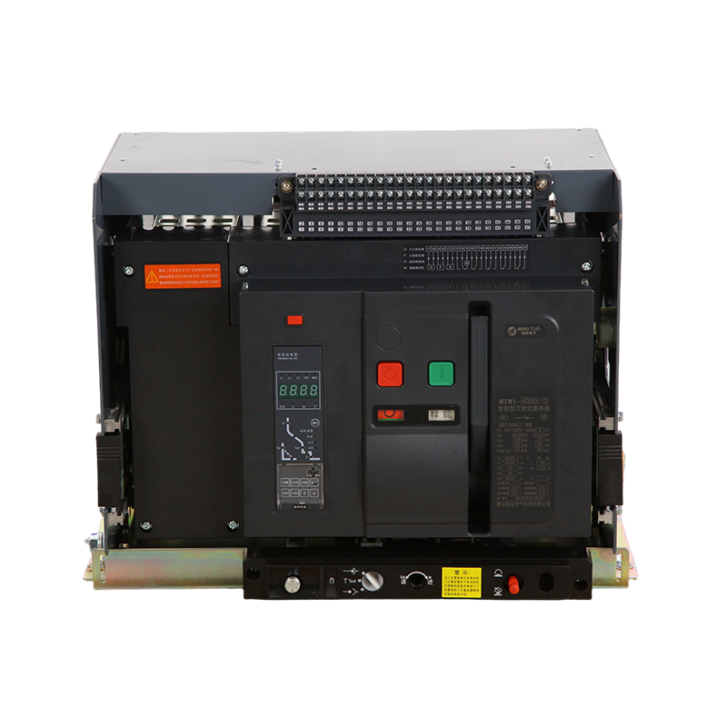
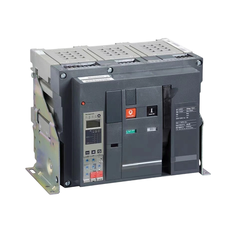
A draw-out air circuit breaker (ACB) is a high-current protective switching device mounted on a chassis that can be physically withdrawn from its cradle or cassette within the switchgear panel without disconnecting any external wiring. Unlike a fixed-mounted circuit breaker — which is bolted permanently into the panel and requires full de-energization of the circuit and physical disconnection of cables before it can be removed — the draw-out design allows the breaker to be rolled or slid out of its operating position through a sequence of defined intermediate positions, isolating it from both the main bus and the control circuits in a safe and controlled manner. The stationary part of the assembly, known as the cradle or withdrawable chassis, remains permanently wired to the incoming and outgoing conductors. All electrical connections between the breaker and the cradle are made through a set of robust, spring-loaded isolating contacts that engage and disengage as the breaker moves between positions.
This seemingly simple mechanical feature has profound practical consequences for the operation, maintenance, and reliability of electrical distribution systems. In industrial plants, data centers, hospitals, and large commercial buildings — environments where continuous power availability is critical and maintenance must be performed safely — the draw-out mechanism transforms what would otherwise be a major planned outage event into a brief, controlled procedure. The breaker can be tested, inspected, serviced, or replaced on a prepared workbench while a spare unit is installed in the cradle, restoring power within minutes rather than hours. This operational flexibility has made the draw-out air circuit breaker the dominant choice for main incomer, bus coupler, and large feeder positions in medium and high-voltage distribution switchgear worldwide.
The draw-out mechanism operates through three mechanically distinct and lockable positions, each with a specific purpose in safe switchgear operation. Understanding these positions is fundamental to operating draw-out switchgear correctly and safely.
In the connected position, the breaker's main isolating contacts are fully engaged with the cradle's bus-side and load-side contacts, and the secondary control circuit plug is connected. The breaker is ready to be closed and carry current normally. All interlocks are satisfied for normal operation. The breaker cannot be racked out of the connected position while it is in the closed (ON) state — an anti-withdrawal interlock prevents movement until the breaker has been opened, protecting against the catastrophic consequences of attempting to break load current with the racking mechanism rather than the arc-quenching contacts.
In the test position, the main isolating contacts are fully disengaged and physically separated from the bus and load conductors, but the secondary control circuit plug remains connected. This allows the breaker's control, protection relay, motor operating mechanism, and auxiliary functions to be operated and tested using the panel's control power supply without any possibility of the main contacts making connection to the live bus. Maintenance technicians can perform complete functional testing — including trip tests from overcurrent and earth fault relays, opening and closing the breaker electrically, and verifying auxiliary contact states — in complete safety with the main circuit isolated. The test position is also used for initial commissioning checks and periodic routine testing without requiring a system outage.
In the disconnected position, both the main isolating contacts and the secondary control circuit plug are fully disengaged. The breaker is completely isolated from all electrical connections within the panel and can be safely withdrawn from the cradle on its guide rails or wheels for full inspection, cleaning, contact maintenance, or replacement. Automatic safety shutters close over the exposed bus-side and load-side contact clusters in the cradle as the breaker withdraws, preventing accidental contact with live conductors during the withdrawal process. These shutters can only be opened by the controlled reintroduction of the breaker into the cradle, providing a critical layer of protection against inadvertent energized contact in what would otherwise be an exposed live bus compartment.
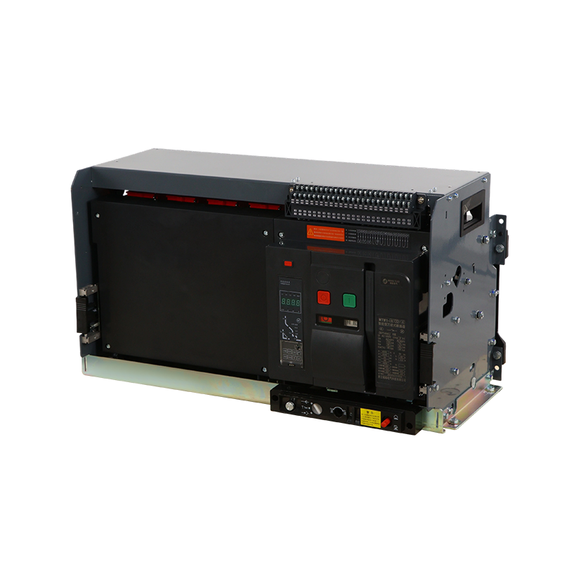
The "air" in air circuit breaker refers to the arc-quenching medium — unlike oil circuit breakers, which extinguish arcs in insulating oil, or SF6 circuit breakers, which use sulfur hexafluoride gas, the ACB interrupts fault current arcs in open air using a system of arc-chute assemblies. Understanding how this works explains both the design's effectiveness and its particular maintenance requirements.
When the breaker contacts separate under fault conditions, an electric arc forms in the gap between the opening contacts. This arc carries the fault current and must be rapidly extinguished to interrupt the circuit. In an ACB, the arc is driven by electromagnetic forces and a set of arc runners into an arc chute — a stack of metal arc-splitter plates arranged perpendicular to the arc path. As the arc enters the chute, it is split into many shorter series arcs between adjacent splitter plates. Each arc segment requires its own re-ignition voltage to sustain, and the combined voltage requirement of all segments quickly exceeds the system voltage, forcing the total arc current to zero and completing the interruption process. The entire sequence, from contact separation to current zero, typically occurs within 20–80 milliseconds depending on fault current magnitude and breaker design.
Draw-out air circuit breakers are designed for high-current applications and are specified across a range of ratings that must be carefully matched to the electrical system's requirements. The primary standards governing ACB design and testing are IEC 60947-2 (Low-voltage switchgear and controlgear — Circuit breakers) and UL 1066 in North American markets, with many manufacturers offering dual-certified products.
| Parameter | Typical Range | Significance |
| Rated Current (In) | 630A – 6300A | Maximum continuous current at rated temperature |
| Rated Ultimate Breaking Capacity (Icu) | 42kA – 100kA | Maximum fault current the breaker can interrupt once |
| Rated Service Breaking Capacity (Ics) | 50–100% of Icu | Fault current level after which breaker remains serviceable |
| Rated Short-Time Withstand Current (Icw) | 42kA – 85kA for 1s | Fault current withstand without tripping (for selectivity) |
| Rated Voltage (Ue) | Up to 1000V AC | Maximum system voltage for which breaker is rated |
| Mechanical Endurance | 10,000 – 20,000 operations | Total open/close cycles before mechanical overhaul |
The distinction between Icu and Ics is particularly important for system designers. A breaker rated at Icu of 85kA can interrupt a fault of that magnitude, but after doing so, it may require replacement or major overhaul before it is fit for continued service. A breaker with Ics equal to 100% of Icu — the highest service breaking capability classification — can interrupt its rated fault current and remain fully serviceable for continued operation, which is an important attribute in critical systems where the breaker must be relied upon after a fault event without immediate replacement.
Modern draw-out air circuit breakers are equipped with microprocessor-based electronic trip units (ETUs) that provide a comprehensive suite of protection functions, metering capabilities, and communication interfaces far beyond what was possible with earlier thermal-magnetic trip mechanisms. The ETU is the intelligence center of the breaker, continuously monitoring current in all phases and the neutral conductor, calculating thermal states, and issuing trip commands to the operating mechanism when any protection threshold is exceeded.
The core protection functions provided by ETUs in draw-out ACBs include overload protection (long-time delay — L), short-circuit protection with a time delay (short-time delay — S), instantaneous short-circuit protection (I), and earth fault protection (G). Each function has independently adjustable pickup current thresholds and time delay settings, allowing the protection engineer to configure the breaker's trip characteristic precisely to achieve discrimination with upstream and downstream devices across the full range of fault current levels. This four-function LSIG protection framework is the standard architecture for ACB ETUs and forms the basis for coordinating protection in complex distribution systems with multiple levels of overcurrent devices.
Beyond protection, advanced ETUs provide true RMS metering of current in each phase and neutral, voltage across each phase and between phases, power factor, active and reactive power, energy consumption, and harmonic distortion levels. This metering data is accessible locally via an integral display and remotely via communication interfaces including Modbus RTU, Modbus TCP/IP, PROFIBUS, PROFINET, IEC 61850, and various manufacturer-proprietary protocols. Integration with building management systems, SCADA platforms, and energy management software allows the breaker's data to contribute to comprehensive power quality monitoring, demand management, and predictive maintenance programs across the facility.
The draw-out air circuit breaker is specified wherever the combination of high current capacity, comprehensive protection, operational flexibility, and maintainability without outages justifies the higher cost compared to fixed-mounted molded case circuit breakers. Several application categories consistently drive ACB specification decisions.
One of the primary justifications for specifying draw-out construction is the ease and safety of maintenance. However, the draw-out mechanism only delivers its availability benefits if a structured maintenance program is actually implemented. Neglecting ACB maintenance is common in practice and leads to contact degradation, mechanism binding, and ETU drift that can result in either nuisance tripping or — more dangerously — failure to trip under genuine fault conditions.
Specifying a draw-out air circuit breaker correctly requires working through a structured selection process that covers electrical ratings, protection requirements, mechanical and environmental factors, and system integration needs.
Zhejiang Mingtuo Electrical Technology Co., Ltd. All Rights Reserved.
Electrical Protection Circuit Breakers Medium Voltage Circuit Breakers Manufacturers Low Voltage Circuit Breakers Factory
