 English
 Français
 Español
 عربى
عربىIndustry News
Home / News / Industry News / How Do Medium-Voltage Vacuum Circuit Breakers Protect Modern Power Distribution Systems?

Content
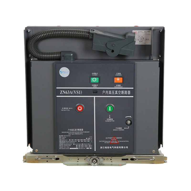
A medium-voltage vacuum circuit breaker (MV VCB) is an electrical switching and protection device designed to make, carry, and interrupt electrical currents under both normal operating conditions and fault conditions in power distribution systems operating within the medium-voltage range — typically defined as 1 kV to 52 kV, with the most common applications falling between 3.6 kV and 40.5 kV. The defining characteristic of this breaker type is its use of a vacuum interrupter as the arc-quenching medium. When the breaker contacts separate under load or fault current, the resulting electrical arc is drawn and extinguished within a sealed vacuum envelope where the absence of gas molecules prevents the arc from being sustained beyond the first natural current zero crossing of the AC waveform.
Medium-voltage vacuum circuit breakers have become the dominant interrupting technology in the 3.6 kV to 40.5 kV range globally, having largely displaced earlier technologies such as oil circuit breakers, air-blast circuit breakers, and SF6 gas circuit breakers in new installations due to their combination of superior interrupting performance, compact physical dimensions, minimal maintenance requirements, environmental safety, and long service life. They are found in utility substations, industrial power distribution switchgear, motor control centers, wind and solar power collection systems, railway traction networks, mining operations, and data center medium-voltage switchgear assemblies worldwide.
The operating principle of a vacuum circuit breaker is fundamentally different from gas or oil-based interrupting technologies. Inside each vacuum interrupter — one per phase — a pair of electrical contacts is housed within a hermetically sealed ceramic or glass envelope evacuated to a pressure of approximately 10⁻³ to 10⁻⁶ Pa. This extreme vacuum level means there are virtually no gas molecules present to sustain an electrical arc after current interruption is initiated.
When the breaker receives a trip signal and the moving contact begins to separate from the fixed contact, the current flowing between them produces a high-energy metallic arc composed of ionized metal vapor vaporized from the contact surfaces themselves. This metal vapor plasma conducts current and maintains the arc for the duration of the half-cycle until the AC current naturally passes through zero. At current zero, the arc plasma rapidly de-ionizes and the metal vapor condenses back onto the contact surfaces and surrounding metallic shield within microseconds — far faster than any gas-based medium can recover its dielectric strength. The vacuum gap then withstands the transient recovery voltage (TRV) imposed by the system, and the interruption is complete. This entire process from contact separation to successful interruption typically occurs within one to two half-cycles of the power frequency, making vacuum circuit breakers among the fastest-interrupting switching devices available at medium voltage.
Understanding the internal architecture of an MV VCB helps engineers and maintenance personnel appreciate the design factors that determine performance, reliability, and service life. The principal components include:
Specifying a medium-voltage vacuum circuit breaker requires a thorough understanding of the rated electrical parameters that define its performance envelope. These ratings are established by international standards including IEC 62271-100 and IEEE C37.04/C37.09, which define test methods and performance requirements for AC high-voltage circuit breakers. The most important parameters are summarized below:
| Parameter | Definition | Typical Range (MV VCB) |
| Rated Voltage (Ur) | Maximum system voltage the breaker is designed for | 3.6 kV – 40.5 kV |
| Rated Normal Current (Ir) | Maximum continuous current at rated voltage without exceeding temperature limits | 630 A – 4,000 A |
| Rated Short-Circuit Breaking Current (Isc) | Maximum symmetrical fault current the breaker can safely interrupt | 16 kA – 63 kA |
| Rated Short-Time Withstand Current (Ik) | Fault current the closed breaker can carry for a specified duration (typically 1–3 s) | 16 kA – 63 kA |
| Rated Peak Withstand Current (Ip) | Maximum instantaneous peak current during the first half-cycle of a fault | 40 kA – 160 kA (peak) |
| Rated Mechanical Endurance | Number of no-load open-close operations the mechanism is designed to perform | 10,000 – 30,000 operations |
| Rated Electrical Endurance | Number of full-load current interruptions at rated current | E1 (1 operation at Isc) to E3 (3 operations at Isc) |
The widespread adoption of vacuum technology in the medium-voltage range is driven by a clear set of performance and operational advantages compared to the SF6, oil, and air-blast technologies it has largely replaced in new installations:
Medium-voltage vacuum circuit breakers are installed in metal-enclosed switchgear assemblies in two primary configurations: withdrawable (also called drawout) and fixed-mounted. The choice between these configurations has significant implications for maintenance access, operational flexibility, and the overall cost of the switchgear installation.
In a withdrawable switchgear design, the circuit breaker module is mounted on a carriage or truck that can be physically rolled or racked out of the switchgear panel to a disconnected or test position without de-energizing the busbar. This design allows the breaker to be removed for inspection, maintenance, or replacement while the switchgear remains energized on adjacent panels — a critical operational advantage in facilities that cannot afford complete power shutdown for maintenance. Withdrawable designs are the standard for most utility and industrial switchgear in the 12 kV to 40.5 kV range and are specified in the majority of new medium-voltage switchgear installations globally.
Fixed-mounted vacuum circuit breakers are permanently bolted into the switchgear panel and cannot be withdrawn without disconnecting the associated busbars and cables. This design results in a simpler, more compact, and lower-cost switchgear panel but requires complete outage of the affected circuit for any breaker maintenance or replacement. Fixed-mounted designs are commonly used in ring main units (RMUs), compact secondary substations, and distribution automation applications where the simplicity and cost savings outweigh the operational flexibility of a withdrawable design.
Selecting a medium-voltage vacuum circuit breaker for a specific application requires systematic evaluation of the electrical system parameters, environmental conditions, operational requirements, and applicable standards. The following criteria should be addressed in every specification process:
Although medium-voltage vacuum circuit breakers are inherently low-maintenance compared to earlier technologies, a structured preventive maintenance program is essential to ensure continued reliable performance and to detect developing faults before they result in service failures. Key maintenance activities include measurement of the vacuum interrupter's contact gap using the graduated scale on the mechanism linkage or specialized contact travel measurement tools — a contact gap that has grown beyond the manufacturer's maximum specification indicates contact erosion that may require interrupter replacement before rated electrical endurance is exhausted.
The integrity of the vacuum in each interrupter should be verified periodically using a high-voltage dielectric withstand test applied across the open contacts — a loss of vacuum reduces the dielectric recovery capability of the interrupter and will be detected as a flashover or significantly reduced withstand voltage during this test. Mechanism lubrication points should be re-greased per the manufacturer's schedule using the specified lubricant grades, as dried or contaminated lubricant is a leading cause of mechanism slow operation, which degrades interrupting performance. Auxiliary contact alignment and wipe, trip coil resistance and insulation, and anti-pumping relay function should all be verified during each maintenance visit. Maintaining a detailed operations log recording each trip and close operation, the associated current level, and any anomalies observed enables accurate tracking of accumulated electrical endurance and supports data-driven decisions about interrupter replacement timing before the end of rated life is reached.


Zhejiang Mingtuo Electrical Technology Co., Ltd. All Rights Reserved.
Electrical Protection Circuit Breakers Medium Voltage Circuit Breakers Manufacturers Low Voltage Circuit Breakers Factory
