 English
 Français
 Español
 عربى
عربىIndustry News
Home / News / Industry News / Molded Case Circuit Breaker Diagram Explained: Components, Wiring, and Types


Content
When a maintenance engineer opens a distribution panel and sees an MCCB with terminals marked 1, 3, 5 and 2, 4, 6, the molded case circuit breaker diagram is what makes the wiring safe to understand. In short, an MCCB diagram tells you where the incoming and outgoing connections go, which internal elements provide overload and short-circuit protection, and what ratings must be respected. Once you learn to read it, you can wire, replace, and specify breakers with confidence.
Every MCCB diagram represents the same core sequence: current flows from the line terminal through the trip unit, the contacts, and the arc extinguishing chamber, then out to the load terminal. The molded case holds these elements together and protects live parts from accidental contact. The table below lists the parts most often shown on an MCCB connection diagram and what each part does.
| Part | Function | What to check on the diagram |
|---|---|---|
| Molded case / frame | Insulating housing | Frame size and pole configuration |
| Line and load terminals | Connection points | Terminal numbering or L/T markers |
| Operating mechanism | Opens and closes the contacts | Manual handle symbol |
| Trip unit | Detects overload and short circuit | Thermal and magnetic elements |
| Contacts | Conduct load current when closed | Normally open contact symbol |
| Arc chamber | Splits and extinguishes the arc | Arc chute symbol |
On most diagrams, the trip unit is drawn as separate thermal and magnetic elements in series with each pole. The thermal element reacts to sustained overload, while the magnetic element responds instantly to a short circuit. That is why an MCCB can replace both a fuse and a switch in one device.
A standard MCCB wiring diagram is easy to follow if you remember the rule: the incoming supply goes to the top terminals, and the outgoing feeder goes to the bottom terminals. Many diagrams use the numbering scheme 1, 3, 5 for line side and 2, 4, 6 for load side.
Always confirm whether you are looking at a schematic diagram or a wiring diagram. A schematic shows the internal logic, while a wiring diagram shows physical connections, so the two drawings can look different even for the same breaker. If you are designing or maintaining a panel, the low and medium voltage electrical protection guide explains where an MCCB sits between the main breaker and the branch circuit.
In many panel layouts, the diagram also marks whether the breaker is wired for top feed or bottom feed. The line and load labels matter because some accessories, such as shunt trips and auxiliary switches, only work when the breaker is oriented and connected as shown.
The MCCB diagram explains why the breaker can handle both overloads and short circuits without external fuses.
In a thermal-magnetic MCCB, each pole has a bimetallic strip that bends as temperature rises. On the diagram, this appears as a curved element in series with the phase conductor. A moderate overload, such as a stalled motor or an overloaded feeder, causes the strip to bend enough to release the operating mechanism after a delay. This delay is intentional because many loads accept a short starting current.
The magnetic element is drawn as a coil or solenoid. When fault current exceeds the trip threshold, the magnetic field pulls the plunger instantly and trips the breaker without waiting for heat. That instantaneous response protects wiring, busbars, and connected equipment from damage.
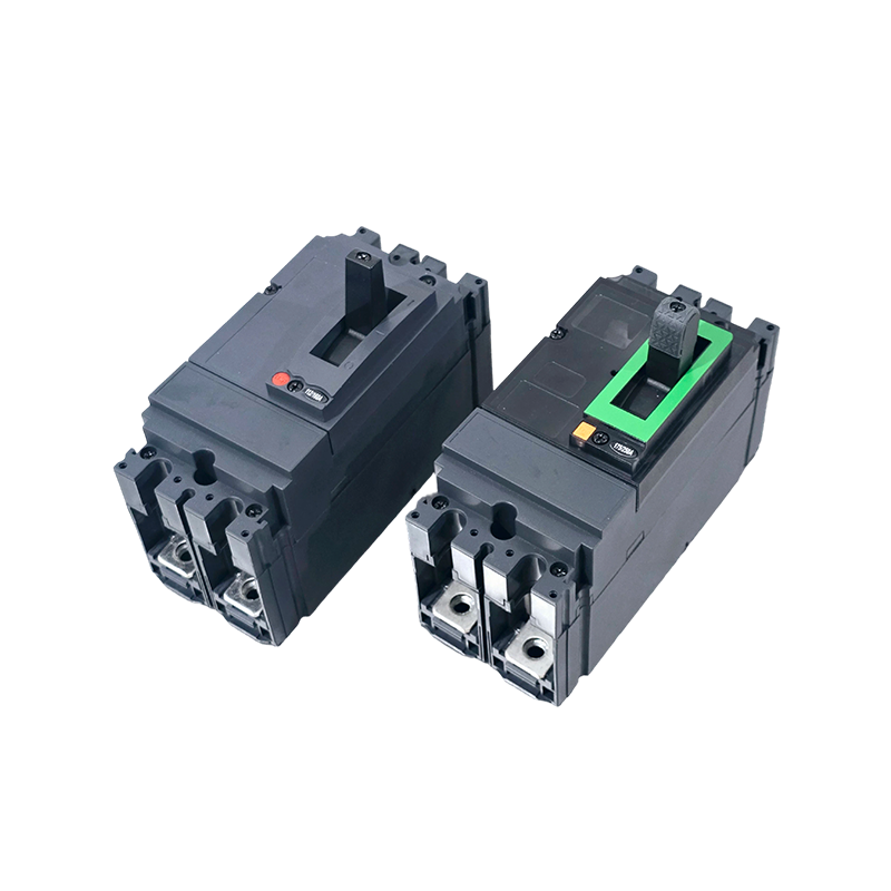
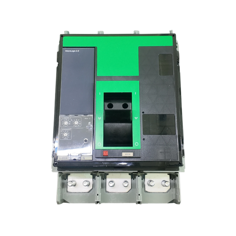
Electronic trip MCCBs replace both elements with current transformers and a microprocessor. On the diagram, you will see CTs around the phase conductors and a control circuit feeding the trip unit instead of a bimetallic element. The MTM1E digital electronic MCCB is one example of this approach: it offers a 50 kA breaking capacity and microprocessor-controlled protection, which makes coordination easier in selective distribution systems.
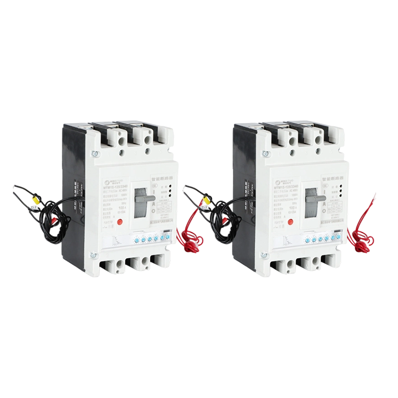 MT-M1 Digital Electronic MCCB, 100-800A, 3/4P, 50kA, Microprocessor-Controlled CMingtuo, China Wholesale MT-M1 Digital Electronic MCCB, 100-800A, 3/4P, 50kA, Microprocessor-Controlled Circuit Breaker Suppliers and MT-...View Product →
The ratings block on an MCCB diagram or nameplate is a short version of the application limits. Match it to the system before you wire or order anything.
These values are not interchangeable. Installing a 10 kA breaker at a point where the available fault current is 25 kA means the breaker may not clear a short circuit safely. The diagram usually shows the breaking capacity on the front label, not inside the internal schematic, but you should treat it as part of the same selection process.
Most MCCB failures in the field trace back to a few simple diagram-reading errors, and the same mistakes can also cause ordering problems.
For solar applications, this last point is critical. The DC side of a PV array has a different arc behaviour than an AC circuit, so a standard AC MCCB cannot simply be reused. A dedicated DC breaker, such as the 1000 V DC molded case circuit breaker for solar panels, is designed with the correct contact spacing and arc chamber for photovoltaic strings.
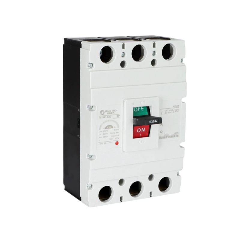
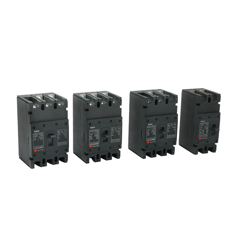 Solar PV DC MCCB Suppliers, DC MCCB in Solar Photovoltaic SystemsMingtuo-DC Molded Case Circuit Breakers Suppliers and Solar PV DC MCCB Factory in China, offer Wholesale PV DC MCCB 1000V 630A Solar Circ...View Product →
Start with the diagram, then match the nameplate to the system characteristics: voltage, current, fault level, and switching duty.
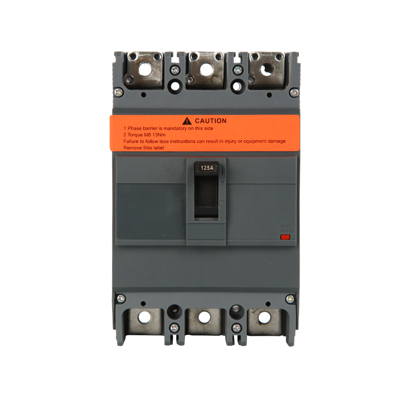
For general low-voltage distribution, a product family with multiple frame sizes simplifies the selection. The EZC series molded case circuit breakers from 100 A to 1600 A cover most panel boards and feeder circuits. If your switchboard needs a specific terminal arrangement, accessory, or drawing, contact our engineering team with the single-line diagram, and we will confirm the equivalent MCCB layout before you order.
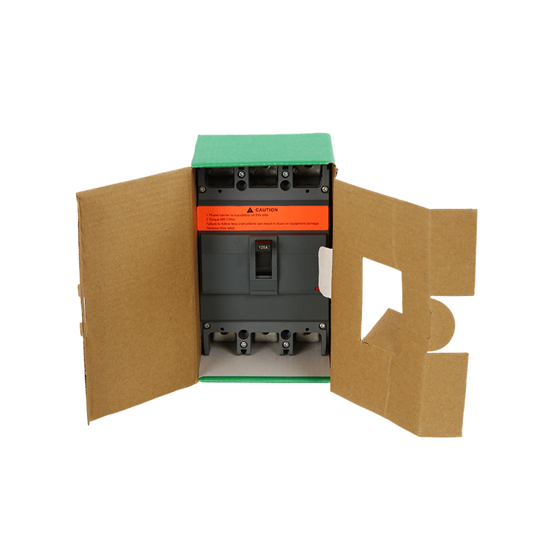 EZC Molded Case Circuit Breaker 100A–1600A for Low-Voltage Power Distribution SuMingtuo, China Wholesale EZC Molded Case Circuit Breaker 100A–1600A for Low-Voltage Power Distribution Suppliers and EZC Molded Case Circ...View Product →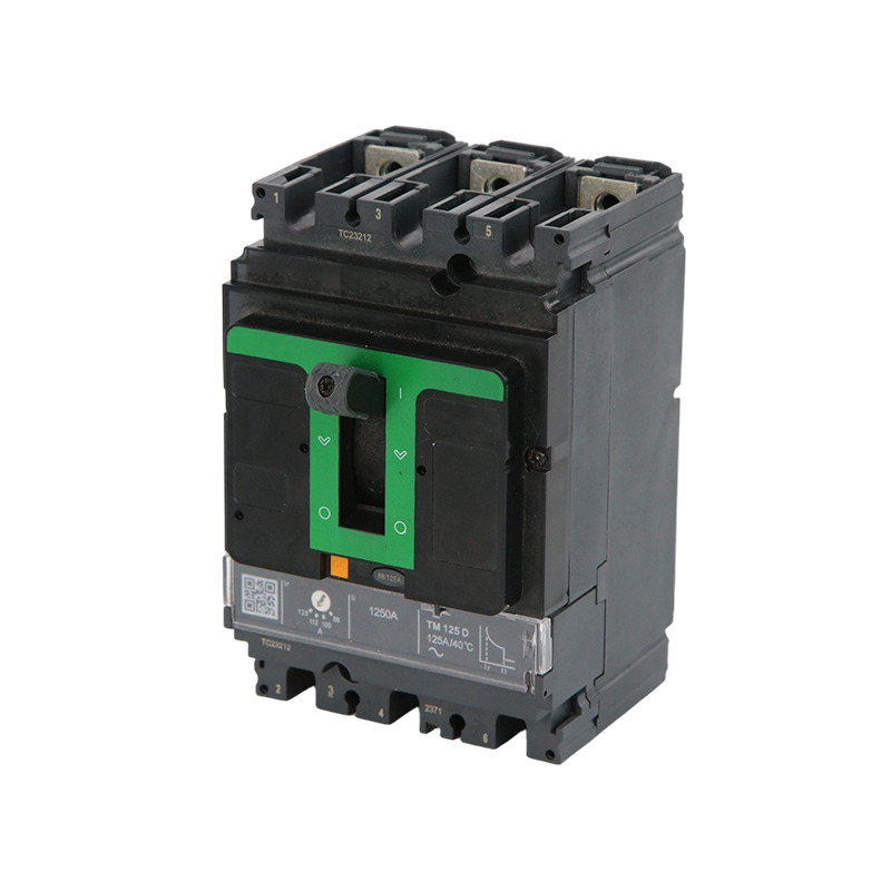
Zhejiang Mingtuo Electrical Technology Co., Ltd. All Rights Reserved.
Electrical Protection Circuit Breakers Medium Voltage Circuit Breakers Manufacturers Low Voltage Circuit Breakers Factory
