 English
 Français
 Español
 عربى
عربىIndustry News
Home / News / Industry News / DC Molded Case Circuit Breaker: Selection Guide for Solar and Industrial DC Systems


Content
Inside a 1000 V photovoltaic combiner box, the fault current never passes through the natural zero that alternating current reaches every half cycle. An AC breaker clears most faults because the current collapses periodically; a DC breaker receives no such assistance. That is why a DC molded case circuit breaker (DC MCCB) is not simply an AC MCCB with a different label, and why installing an AC-only breaker on a DC circuit is one of the most common and dangerous mistakes in solar and industrial DC power systems.
The short answer for specifiers and buyers is straightforward: choose a breaker with an explicit DC voltage rating, a DC breaking capacity above the prospective fault current at the installation point, and a pole configuration that matches the system voltage and grounding. The sections that follow explain why these conditions exist and how they should shape your purchasing decision.
In an AC circuit, the arc inside the breaker is extinguished naturally as the current passes through zero. In a DC circuit, the arc burns continuously until the breaker forces the current to zero. A DC MCCB manages this duty with deeper arc chutes, magnetic blow-out plates, contact materials that resist DC arcing, and an operating mechanism designed for fast, positive contact separation. The result is a breaker that can interrupt a DC fault at its rated voltage and extinguish the arc before the contacts weld or the arc flashes over.
| Comparison point | AC MCCB | DC MCCB |
|---|---|---|
| Arc extinction | Current self-extinguishes near zero | Breaker must force the arc to zero |
| Rated voltage | AC voltage only, such as 380/415 V AC | DC voltage proven by testing, such as 250-1500 V DC |
| Breaking capacity | Tested under AC conditions | Tested under DC conditions with a defined time constant |
| Pole configuration | Pole count follows the number of phases | Poles are often connected in series to share DC voltage |
| Typical duty | General low-voltage distribution | Solar, battery storage, traction, industrial DC |
The table reflects practical electrical behaviour. A pole in a DC MCCB must survive the continuous arc sustained on a single DC bus, and manufacturers verify pole wiring, arc chute geometry, and contact timing against DC breaking tests. When a product page lists only AC ratings, the safe assumption is that the breaker was not designed for DC service.
Interruption difficulty also depends on the source. Photovoltaic panels limit short-circuit current, while batteries and charged DC bus bars can deliver very high currents with a long time constant. The breaker must be selected for the worst-case source at the installation point, not for the average operating load.
DC MCCBs appear wherever DC power is generated, stored, converted, or consumed in meaningful quantity. The fastest-growing application is photovoltaic generation. String voltages on commercial and utility-scale plants commonly reach 1000 V, and 1500 V arrays are becoming standard in new designs.
In these settings, DC MCCBs are often preferred over fuses because they provide resettable protection, a visible open position, and the ability to lock out a circuit for maintenance.
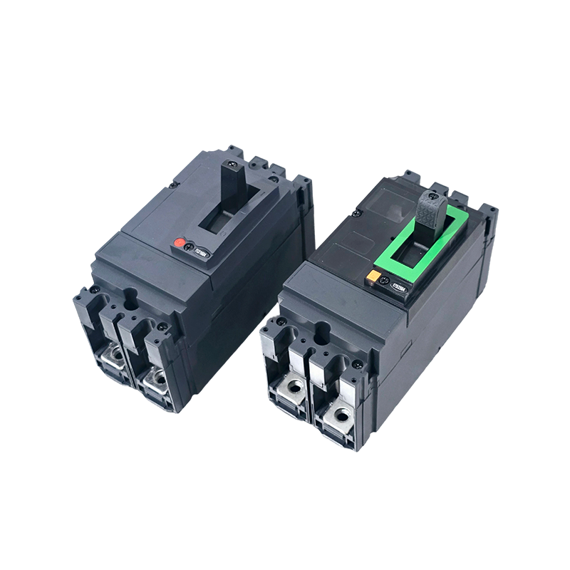
For PV installations, the breaker must be rated for the full array voltage and the available fault current at its mounting point. A dedicated 1000 V DC breaker such as the PV DC MCCB for solar panel protection covers 630 A capacity, which suits large combiner boxes and the DC inputs of centralized inverters.
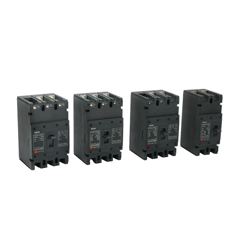 Solar PV DC MCCB Suppliers, DC MCCB in Solar Photovoltaic SystemsMingtuo-DC Molded Case Circuit Breakers Suppliers and Solar PV DC MCCB Factory in China, offer Wholesale PV DC MCCB 1000V 630A Solar Circ...View Product →
Rated voltage is the first filter. AC MCCBs are usually marked with AC values only, and those values do not transfer to DC. Look for an explicit DC rating on the nameplate and in the manufacturer's data sheet, and check the pole configuration table before you compare prices.
The rated DC voltage must be equal to or greater than the maximum system voltage, including the open-circuit voltage of a PV array at low temperature. Three procurement values matter most: the rated current for continuous load, the rated breaking capacity under DC conditions, and the available fault current at the breaker location. A 630 A DC breaker used as a main PV switch, for instance, needs a DC breaking capacity above the maximum fault current delivered by the upstream source.
Also check the pole count. Two or more poles of a single breaker can be connected in series to reach higher DC voltages, but this arrangement is valid only when the manufacturer explicitly approves it and provides the corresponding test data.
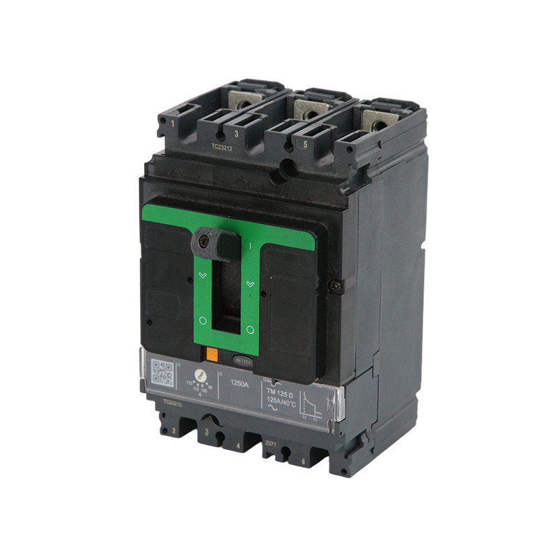
Thermal-magnetic trip units, combining a bimetallic strip for overload protection and a magnetic coil for short-circuits, remain the workhorse of DC MCCBs. Electronic trip units go further: a microprocessor measures current and provides independently adjustable long-time, short-time, instantaneous, and ground-fault settings. When load profiles change or coordination with upstream breakers is tight, a digital electronic MCCB with microprocessor control simplifies setting changes and reduces nuisance tripping.
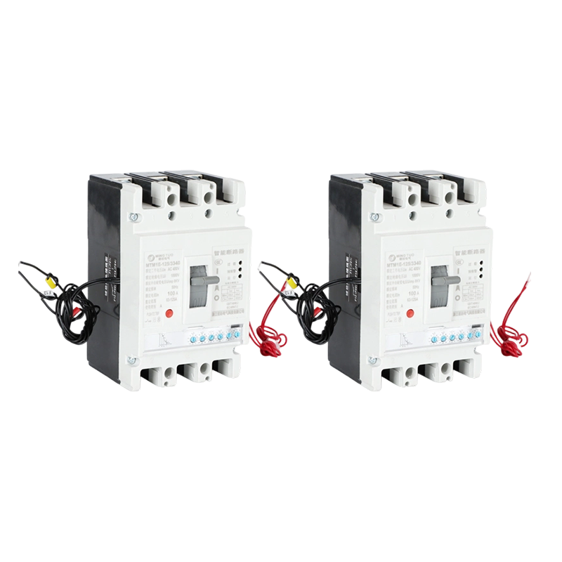 MT-M1 Digital Electronic MCCB, 100-800A, 3/4P, 50kA, Microprocessor-Controlled CMingtuo, China Wholesale MT-M1 Digital Electronic MCCB, 100-800A, 3/4P, 50kA, Microprocessor-Controlled Circuit Breaker Suppliers and MT-...View Product →
IEC 60947-2 governs low-voltage switchgear, and UL 489 is the corresponding North American standard. Request the test report that shows the DC breaking capacity and the time constant used during testing. A breaker that passed a 1000 V DC test with a very short time constant may not be suitable for a battery bank with a long time constant and high prospective short-circuit energy. If you are designing protection beyond a single breaker, our low-voltage and medium-voltage electrical protection guide explains how MCCBs fit into a complete coordination scheme.
Procurement is only part of the job. DC MCCBs carry installation rules that are easy to overlook and expensive to ignore.
These details look minor on paper, but they dominate field failure reports. A breaker with reversed polarity can clear a small overload yet fail completely at high short-circuit current, converting a routine protection point into an arc fault source.
Before you place an order, confirm the following points in writing with the supplier.
A DC MCCB is a safety device, not a commodity. The extra minutes spent verifying ratings and wiring rules are inexpensive compared with a welded contact, a damaged inverter, or an arc flash investigation. If the application is unusual or the fault calculation is uncertain, discuss the project with our engineers before committing to a specific model.
Zhejiang Mingtuo Electrical Technology Co., Ltd. All Rights Reserved.
Electrical Protection Circuit Breakers Medium Voltage Circuit Breakers Manufacturers Low Voltage Circuit Breakers Factory
