 English
 Français
 Español
 عربى
عربىIndustry News
Home / News / Industry News / What Makes Indoor Vacuum Circuit Breakers the Right Choice for MV Systems?

Content
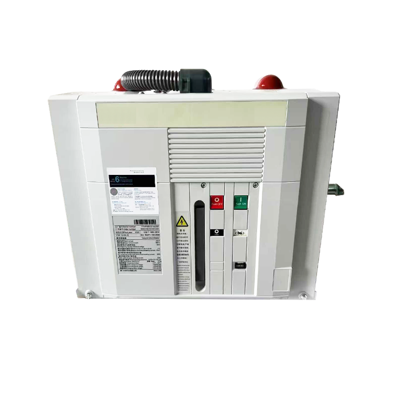
An indoor vacuum circuit breaker (VCB) is a medium-voltage switching and protection device that uses vacuum as the arc-quenching medium to interrupt fault currents and isolate electrical circuits within enclosed indoor switchgear installations. Unlike oil circuit breakers or air-blast circuit breakers, which rely on liquid or compressed gas to extinguish the arc formed when contacts separate under load, a vacuum circuit breaker contains its contact assembly inside a highly evacuated ceramic or glass envelope — typically maintained at a vacuum pressure of 10⁻³ to 10⁻⁷ Pa — where the absence of gas molecules makes arc sustenance virtually impossible after the current zero crossing.
Indoor VCBs are designed for installation inside metal-clad switchgear panels, ring main units, and motor control centers in facilities such as substations, industrial plants, commercial buildings, data centers, and utility distribution networks. They operate across the medium-voltage range, most commonly from 3.6 kV to 40.5 kV, and are available in rated normal currents from 630 A to 4000 A with short-circuit breaking capacities typically ranging from 16 kA to 63 kA. Their compact form factor, minimal maintenance requirements, and environmental cleanliness make them the dominant circuit breaker technology in modern indoor medium-voltage applications worldwide.
The arc interruption mechanism in a vacuum circuit breaker is fundamentally different from that in other breaker technologies and is central to understanding why VCBs perform so reliably over extended service lives. When the breaker receives a trip signal — either from a protection relay detecting an overcurrent, earth fault, or differential condition — the operating mechanism rapidly separates the moving contact from the fixed contact inside the vacuum interrupter bottle.
As the contacts part, the current continues to flow briefly through a metallic vapor arc formed from the evaporation of contact material — typically a copper-chromium alloy. This arc exists only as long as current flows. At the natural current zero crossing of the AC waveform — which occurs 100 times per second at 50 Hz — the arc extinguishes because the vacuum environment cannot sustain ionization without a gas medium. The dielectric strength of the vacuum gap recovers almost instantaneously after current zero, preventing arc re-ignition even at high recovery voltages. The entire interruption event, from contact separation to final arc extinction, typically takes less than one half-cycle — under 10 milliseconds — making vacuum circuit breakers among the fastest-clearing protection devices available.
Understanding the internal structure of an indoor VCB helps engineers and maintenance personnel appreciate how each component contributes to overall performance and longevity.
The vacuum interrupter is the sealed envelope containing the contact pair. It is constructed from high-alumina ceramic or borosilicate glass to maintain vacuum integrity over decades of operation. The contacts inside are made from copper-chromium (CuCr) alloy, which offers an optimal balance of electrical conductivity, arc erosion resistance, and low chopping current characteristics. The contact geometry — often a spiral groove or cup-shaped design — imparts a transverse magnetic field that drives the arc into a diffuse, rotating mode rather than allowing it to concentrate at a fixed point, which would cause rapid contact erosion and reduced interrupting capability.
The operating mechanism provides the mechanical energy needed to open and close the contacts with the speed and force required for reliable interruption and making. Three mechanism types are in common use: spring-charged mechanisms store energy in a pre-charged closing spring and a separate trip spring, released by solenoid actuators on command; magnetic actuator mechanisms use a permanent magnet to hold contacts in both open and closed positions with a brief pulse of current required only to change state, offering exceptionally long mechanical life; and motorized spring mechanisms charge automatically after each operation, ensuring the breaker is always ready for the next switching cycle without manual intervention.
The three vacuum interrupters — one per phase — are supported within an insulating framework made from epoxy resin or glass-fiber reinforced polymer. This structure provides phase-to-phase and phase-to-earth insulation, mechanical rigidity under electromagnetic forces during fault current interruption, and resistance to humidity and surface tracking. In draw-out type VCBs, the entire breaker module is mounted on a chassis that can be rolled into or out of the switchgear panel on guide rails, allowing safe isolation for inspection and maintenance without disconnecting busbars.
Indoor vacuum circuit breakers are manufactured and tested to rigorous international standards — primarily IEC 62271-100 for AC circuit breakers and ANSI/IEEE C37.04 for North American markets. The following table summarizes the typical rating ranges encountered in indoor VCB specifications:
| Parameter | Typical Range | Common Standard Values |
| Rated Voltage | 3.6 kV – 40.5 kV | 7.2 kV, 12 kV, 24 kV, 36 kV |
| Rated Normal Current | 630 A – 4000 A | 630 A, 1250 A, 2000 A, 3150 A |
| Rated Short-Circuit Breaking Current | 16 kA – 63 kA | 20 kA, 25 kA, 31.5 kA, 40 kA |
| Rated Short-Circuit Making Current (Peak) | 40 kA – 160 kA | 2.5× the breaking current (IEC) |
| Mechanical Endurance Class | M1 or M2 | M1: 2,000 ops; M2: 10,000 ops |
| Electrical Endurance Class | E1 or E2 | E2: no contact replacement required over rated life |
| Operating Temperature Range | −25°C to +55°C | Altitude derating above 1000 m |
The distinction between M1 and M2 mechanical endurance classes, and between E1 and E2 electrical endurance classes, is significant for applications involving frequent switching operations — such as capacitor bank switching, motor starting, or arc furnace control — where a higher endurance class directly translates into longer contact life and reduced maintenance intervals.
The widespread adoption of vacuum circuit breakers in indoor medium-voltage applications over the past four decades is the result of genuine technical advantages relative to the SF₆ gas circuit breakers, minimum oil circuit breakers, and air-blast circuit breakers they have largely replaced.
Indoor VCBs serve as the primary protection and switching device across a wide range of medium-voltage applications, each placing different demands on the breaker in terms of switching frequency, load type, and fault current magnitude.
In utility and industrial distribution substations, indoor VCBs are installed in metal-clad switchgear as incoming feeder breakers, bus coupler breakers, and outgoing feeder breakers. They provide fault protection coordinated with upstream and downstream protection devices, enabling selective fault clearance that isolates only the faulted section while maintaining supply continuity to unaffected feeders. Rated at 12 kV or 24 kV with breaking currents of 25 kA to 40 kA, these breakers must combine high reliability with rapid trip response to limit fault energy and minimize equipment damage.
Large medium-voltage motors — typically above 1 MW — require a dedicated vacuum circuit breaker for starting, running protection, and emergency tripping. Motor feeder VCBs must handle high inrush currents during direct-on-line starting, which can reach 6 to 8 times the full-load current, without nuisance tripping. They must also respond to protection relay signals for thermal overload, locked rotor, phase unbalance, and earth fault conditions within milliseconds to prevent motor winding damage. Class M2 mechanical endurance is typically specified for motor switching duty due to the frequent start-stop cycling involved.
Transformer feeder VCBs protect medium-voltage to low-voltage distribution transformers from external faults, internal winding faults detected by Buchholz or differential relays, and overtemperature conditions. They are required to make onto and interrupt the high inrush magnetizing current that flows when a transformer is energized — which can reach 8 to 12 times rated current — without misoperation, requiring careful coordination of the protection relay's inrush restraint settings with the breaker's operating characteristics.
Switching capacitor banks for power factor correction generates high-frequency transient inrush currents and transient recovery voltages that stress circuit breaker contacts and insulation severely. VCBs used for capacitor switching must be specifically rated and tested for this duty class — designated C1 (low probability of restrike) or C2 (very low probability of restrike) under IEC 62271-100. Capacitor switching VCBs incorporate contact materials and gap geometries specifically optimized to minimize restrike probability, which can cause dangerous overvoltages throughout the connected network.
Although indoor VCBs require far less routine maintenance than their oil or gas counterparts, periodic condition assessment is still essential to confirm continued reliable performance over the 25 to 30-year expected service life of the equipment.
Selecting the correct indoor VCB for a specific application requires a systematic evaluation of the electrical system parameters, the load characteristics, the switchgear it will be installed in, and the applicable standards. The following criteria should be confirmed before finalizing a specification:


Zhejiang Mingtuo Electrical Technology Co., Ltd. All Rights Reserved.
Electrical Protection Circuit Breakers Medium Voltage Circuit Breakers Manufacturers Low Voltage Circuit Breakers Factory
