 English
 Français
 Español
 عربى
عربى
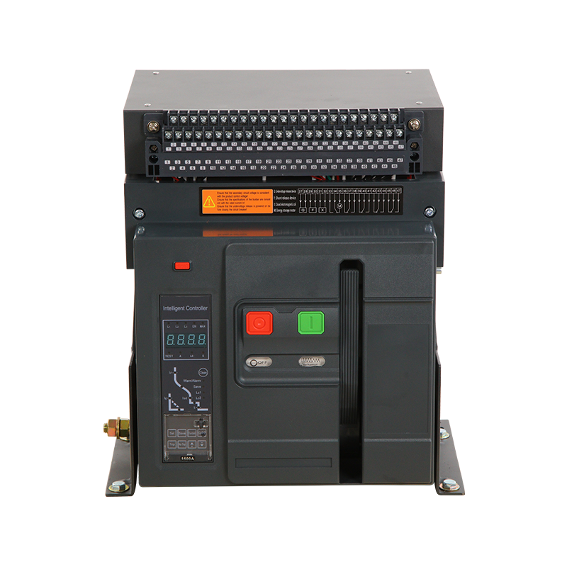
ACB Circuit Breaker: What It Is, How It Works, and When to Use It
Content
- 1 What Is an ACB Circuit Breaker?
- 2 How an ACB Circuit Breaker Works
- 3 Key Components of an ACB and Their Functions
- 4 Protection Functions Built Into Modern ACB Trip Units
- 5 Fixed vs. Withdrawable ACB: Choosing the Right Configuration
- 6 ACB vs. MCCB: Understanding When to Use Each
- 7 Key Factors to Consider When Selecting an ACB
- 8 Maintenance Requirements for ACB Circuit Breakers
In large-scale electrical systems — power plants, industrial facilities, commercial buildings, and data centers — protecting equipment and personnel from overcurrents and short circuits is a non-negotiable engineering requirement. The Air Circuit Breaker, commonly known as an ACB circuit breaker, is one of the most important protective devices used at the low-voltage end of high-power distribution networks. Unlike smaller molded case circuit breakers (MCCBs) designed for lower current applications, ACBs are engineered to handle extremely high fault currents, offer advanced trip protection, and provide the operational flexibility demanded by complex power systems. This article explains exactly what an ACB is, how it works internally, what its key components do, and how to make the right selection for your specific application.
What Is an ACB Circuit Breaker?
An Air Circuit Breaker is a type of circuit breaker that uses air at atmospheric pressure as the arc-extinguishing medium. When the breaker interrupts a fault current, the electrical arc that forms between the separating contacts is quenched by directing it into an arc chute — a structured series of metallic plates that cools, elongates, and ultimately extinguishes the arc without the need for oil, vacuum, or SF6 gas. This air-based interruption technology is what gives the ACB its name and its defining characteristic.
ACBs are typically rated for low-voltage applications — generally systems operating at up to 1,000V AC — and are designed to carry and interrupt very high currents. Rated current capacities commonly range from 630A to 6,300A, with short-circuit breaking capacities that can reach 100kA or more in heavy-duty industrial models. They are the standard choice for main incomer panels, bus-coupler positions, and large feeder circuits in switchgear assemblies where reliable, adjustable overcurrent protection is essential.
How an ACB Circuit Breaker Works
Under normal operating conditions, current flows through the ACB via a set of main contacts that remain closed. The breaker continuously monitors electrical parameters through its electronic trip unit — typically measuring current in all phases plus the neutral. When the trip unit detects an abnormal condition, it sends a signal to the operating mechanism, which releases stored mechanical energy (usually from a spring-charged mechanism) to rapidly open the main contacts and interrupt the circuit.
The moment the contacts begin to separate under load, an electrical arc forms between them due to the ionization of air. This arc, if left unchecked, would sustain current flow and cause severe damage. To extinguish it, the ACB uses an arc chute assembly — a series of ferromagnetic arc splitter plates arranged in a stack. A magnetic blow-out system (generated either by permanent magnets or by the fault current itself passing through blow-out coils) drives the arc upward into the chute. Inside the chute, the arc is split into multiple shorter arcs in series, each of which has its own reignition voltage requirement. The cumulative reignition voltage required exceeds the system voltage, causing the arc to extinguish rapidly and completely.
The Role of the Electronic Trip Unit
The electronic trip unit (ETU) is the intelligence of the ACB. It continuously samples the current waveform in real time and compares it against programmed thresholds. Modern ETUs offer multiple independently adjustable protection functions, allowing the ACB to be precisely tuned for the specific characteristics of the circuit it protects. This programmability is one of the key advantages of ACBs over simpler protective devices.
Key Components of an ACB and Their Functions
Understanding the internal architecture of an ACB helps clarify why these devices are so reliable and versatile in demanding power environments. The major components each serve a distinct and critical role:
- Main Contacts: Heavy-duty silver-alloy or copper-tungsten contacts that carry rated current continuously. They are designed to withstand thousands of mechanical operations and the thermal stress of fault current interruption.
- Arcing Contacts: Sacrificial contacts that make first and break last during operation, absorbing the arc energy to protect the main contacts from erosion and extending overall contact life.
- Arc Chute Assembly: The arc extinction chamber containing deionizing splitter plates. The design and geometry of the chute determines the breaker's arc interruption speed and breaking capacity.
- Operating Mechanism: A spring-charged mechanical assembly that stores energy during charging and releases it on command to open or close the contacts with consistent, high-speed force regardless of operator input.
- Electronic Trip Unit (ETU): The microprocessor-based protection relay built into the breaker that monitors current, detects faults, and initiates tripping. It replaces older thermal-magnetic trip mechanisms with precise, adjustable digital logic.
- Current Transformers (CTs): Built-in CTs in each pole measure the current waveform and feed that data to the ETU for continuous real-time monitoring.
- Shunt Trip and Closing Coils: Electrically operated actuators that allow the breaker to be opened or closed remotely via control signals from a SCADA system, building management system, or remote operator panel.</li shshunt>
Protection Functions Built Into Modern ACB Trip Units
One of the defining strengths of the ACB over simpler circuit breakers is the range of protection functions available through its electronic trip unit. These functions can typically be enabled, disabled, and adjusted during commissioning to suit the precise requirements of each installation:
| Protection Function | Abbreviation | What It Protects Against |
| Long-Time Delay | LTD / Ir | Sustained overload currents |
| Short-Time Delay | STD / Isd | High overcurrents with intentional time delay for coordination |
| Instantaneous | INST / Ii | Severe short-circuit faults requiring immediate interruption |
| Ground Fault | GFP / Ig | Earth leakage currents that could cause fires or equipment damage |
| Neutral Protection | N/A | Overcurrent on the neutral conductor in 4-pole configurations |
| Zone Selective Interlocking | ZSI | Enables fast tripping at the fault location while maintaining coordination upstream |
Zone Selective Interlocking deserves special mention. In a tiered distribution system where multiple ACBs are installed in series, ZSI allows the breaker closest to the fault to trip instantly while upstream breakers remain closed, maintaining power to the rest of the system. Without ZSI, all breakers in the chain might trip with a time delay to allow coordination, potentially causing much wider outages. ZSI dramatically improves system uptime in critical facilities.
Fixed vs. Withdrawable ACB: Choosing the Right Configuration
ACBs are available in two mounting configurations — fixed and withdrawable — and the choice between them has significant implications for maintenance procedures and system availability.
Fixed ACBs
Fixed ACBs are bolted directly into the switchgear panel and are permanently connected to the busbars and outgoing cables. They are less expensive than withdrawable versions and are suitable for applications where the breaker does not need to be regularly removed for testing or replacement. However, maintenance requires the circuit to be de-energized completely, which can be disruptive in systems that demand high availability.
Withdrawable ACBs
Withdrawable ACBs are mounted on a sliding cradle and can be racked out from the panel into a test position — where the control circuits remain connected but the main power contacts are isolated — or fully removed from the panel without disconnecting any wiring. This allows the trip unit to be tested, the breaker to be inspected, and replacement units to be installed while the panel remains energized. For hospitals, data centers, and industrial facilities where downtime is extremely costly, withdrawable ACBs are almost always the correct choice despite their higher cost.
ACB vs. MCCB: Understanding When to Use Each
A common question among electrical engineers and panel builders is when to specify an ACB versus a Molded Case Circuit Breaker (MCCB). The distinction is primarily about current rating, breaking capacity, and the need for adjustable protection settings.
- Use an MCCB for distribution feeders, branch circuits, and motor protection where rated currents are below 630A and a fixed or limited-adjustment trip characteristic is acceptable
- Use an ACB as the main incomer or bus coupler in main distribution boards (MDBs) where rated currents exceed 630A and full programmability of protection settings is required
- Choose an ACB when short-circuit breaking capacity requirements exceed what MCCBs in the same current range can offer
- Choose an ACB when the installation requires remote operation, metering integration, or communication via Modbus, Profibus, or other industrial protocols
- Choose an MCCB when space is limited and a compact form factor is necessary, as ACBs require significantly more panel depth and width
Key Factors to Consider When Selecting an ACB
Selecting the correct ACB for a specific application requires careful evaluation of several electrical and operational parameters. Getting any of these wrong can result in nuisance tripping, failure to interrupt fault currents, or equipment damage.
- Rated Current (In): The continuous current the breaker can carry at its rated ambient temperature without tripping. Select a rating that matches or slightly exceeds the maximum expected load current, with consideration for derating in high-temperature environments.
- Rated Short-Circuit Breaking Capacity (Icu/Ics): The maximum prospective fault current the ACB can safely interrupt. This must be equal to or greater than the maximum fault level at the point of installation, calculated from the transformer impedance and upstream network impedance.
- Number of Poles: Three-pole ACBs are standard for three-phase systems. Four-pole versions with a switched or protected neutral pole are required in TN-S and TT earthing systems or where harmonic distortion creates significant neutral currents.
- Operating Voltage: Verify that the ACB's rated voltage matches the system voltage. Most low-voltage ACBs are rated for 415V or 690V AC; always confirm the insulation and interruption ratings match system requirements.
- Mechanical and Electrical Endurance: ACBs are rated for a specific number of mechanical operations (open-close cycles) and electrical operations under load. For applications with frequent switching — such as bus-tie breakers or generator incomers — select a model rated for high operational endurance.
Maintenance Requirements for ACB Circuit Breakers
ACBs are robust devices designed for long service life, but they require periodic maintenance to ensure reliable operation. Neglecting maintenance is one of the most common causes of ACB failure during actual fault conditions — precisely when reliable operation is most critical.
Manufacturers typically recommend inspection intervals of 12 to 24 months depending on operating frequency and environmental conditions. Key maintenance tasks include cleaning the arc chute plates to remove carbon deposits from previous arc events, inspecting and measuring main and arcing contact erosion, lubricating the operating mechanism per manufacturer specifications, testing the trip unit function using a secondary injection test set, and verifying the operation of all auxiliary switches, shunt trips, and closing coils. For withdrawable ACBs, the racking mechanism and cradle contact fingers should also be inspected and cleaned regularly to ensure reliable electrical connection when racked in.
When an ACB has operated to clear a major fault, it should always be inspected before being returned to service. A severe fault interruption can cause significant arc chute erosion and contact wear even in a single operation, and returning a damaged breaker to service without inspection is a serious safety risk. Maintaining a structured maintenance schedule and keeping detailed service records for each ACB is a fundamental requirement of responsible electrical asset management.
Recommended Products


Zhejiang Mingtuo Electrical Technology Co., Ltd. All Rights Reserved.
Electrical Protection Circuit Breakers Medium Voltage Circuit Breakers Manufacturers Low Voltage Circuit Breakers Factory
