 English
 Français
 Español
 عربى
عربىIndustry News
Home / News / Industry News / What Key Parameters Should You Check Before Selecting a Vacuum Circuit Breaker?

Content
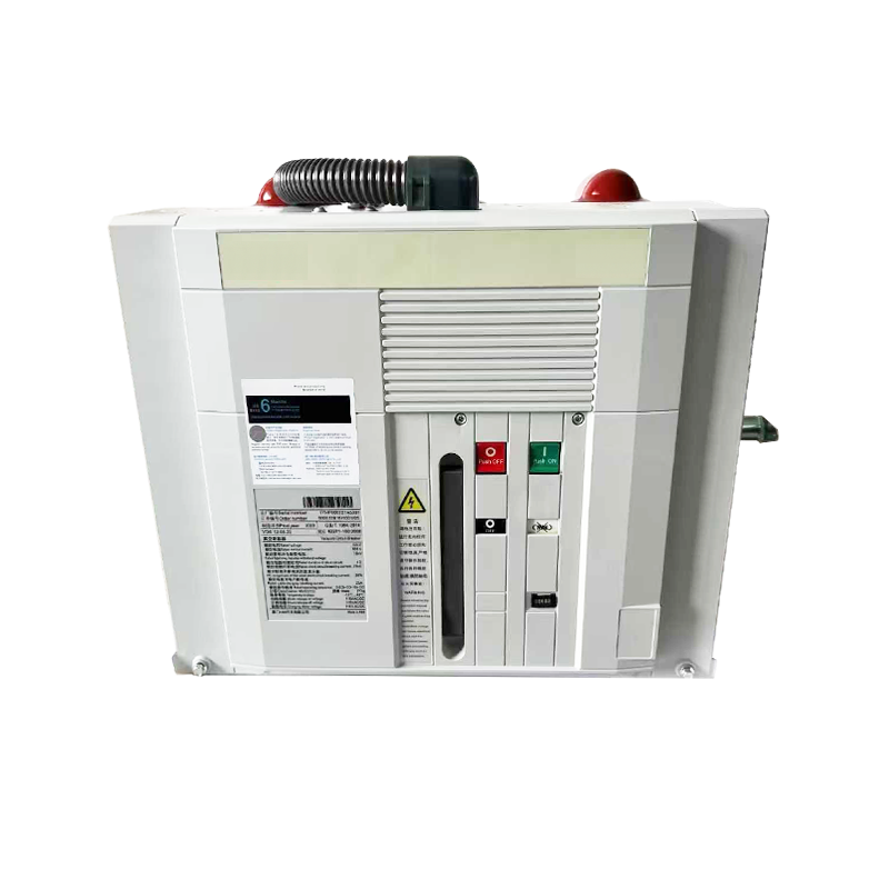
A vacuum circuit breaker (VCB) interrupts fault current by separating its contacts inside a sealed vacuum interrupter, where the absence of gas molecules means an arc formed between the contacts extinguishes almost immediately — typically within the first current zero crossing after contact separation. Compared to oil, air-blast, or SF6 circuit breakers, VCBs offer faster arc extinction, a much longer electrical life (commonly 10,000 or more operations at rated current), minimal maintenance requirements, and no risk of fire or toxic gas release. These advantages have made them the dominant choice for medium-voltage switchgear in the range of 3.6 kV to 40.5 kV, covering industrial plants, utility distribution substations, commercial buildings, mining operations, and renewable energy installations.
Despite their reliability, VCBs are not a one-size-fits-all device. Voltage class, rated current, short-circuit breaking capacity, operating mechanism, and the specific characteristics of the load being protected all influence which breaker is correct for a given application. Selecting a VCB that is undersized for its fault level, mismatched to its load type, or incompatible with its switchgear panel will compromise both protection and equipment lifespan. This guide walks through every critical selection parameter in practical terms.
The first and most fundamental selection criterion is the rated maximum voltage of the breaker, which must equal or exceed the highest voltage that will appear at the breaker terminals under any operating condition, including temporary overvoltages during switching or fault events. VCBs are manufactured in standard voltage classes defined by IEC 62271-100 and ANSI/IEEE C37.04. Common classes include 7.2 kV, 12 kV, 17.5 kV, 24 kV, and 40.5 kV for medium-voltage applications.
Do not select a breaker rated exactly at the nominal system voltage. A 6.6 kV distribution system should use a 7.2 kV rated breaker, and an 11 kV system requires a 12 kV class breaker, because the rated maximum voltage accounts for system voltage tolerances and transient overvoltages. Equally important is the rated power-frequency withstand voltage and the rated lightning impulse withstand voltage (BIL), which confirm the breaker can survive the dielectric stresses imposed by lightning strikes and switching surges on the connected network.
The rated normal current is the continuous current the breaker can carry indefinitely without exceeding the temperature limits of its contacts, conductors, and terminals. This value must be matched to the maximum continuous load current of the circuit being protected, with an appropriate safety margin. Standard rated currents for medium-voltage VCBs are 630 A, 1250 A, 1600 A, 2000 A, 2500 A, and 3150 A.
When calculating the required current rating, account for the full load current of the largest motor or transformer being protected, plus any additional loads on the same feeder. For transformer feeders, use the transformer's full load current at the primary voltage, not the nameplate kVA alone. For motor feeders, include the service factor and potential future load growth. Selecting a current rating with at least 20–25% headroom above the calculated maximum load current is good practice and avoids nuisance thermal aging of the breaker contacts over its service life.
The short-circuit breaking capacity (also called the rated short-circuit breaking current or Isc) is arguably the most critical safety parameter in VCB selection. It defines the maximum prospective fault current the breaker can safely interrupt without damage to the interrupter or loss of containment. If the actual fault level at the installation point exceeds the breaker's rated breaking capacity, the breaker may fail to interrupt the fault, resulting in sustained arcing, explosion of the vacuum interrupter, and potentially catastrophic damage to the switchgear and connected equipment.
The prospective fault current at any point in the network must be calculated using a short-circuit study, taking into account the source impedance of the utility supply, the impedance of all transformers and cables between the source and the breaker, and the contribution of any local generators or large motors. Common rated breaking currents for medium-voltage VCBs are 16 kA, 20 kA, 25 kA, 31.5 kA, and 40 kA (symmetrical RMS). Always select a breaker whose rated breaking current exceeds the calculated prospective fault current at the installation point, including future network reinforcement scenarios that might increase the fault level.
Closely related is the rated short-time withstand current (Ik), which is the fault current the breaker can carry for a specified duration (typically 1 or 3 seconds) without damage. This parameter is relevant for bus-section and bus-coupler breakers that may carry fault current while upstream protection operates.
The nature of the load connected to the circuit significantly influences VCB selection, because different load types impose different stresses on the vacuum interrupter during switching.
Switching medium-voltage motors is one of the most demanding VCB applications. At the moment of energization, a motor draws an inrush current of 6–8 times its full load current. More critically, when a running motor is switched off, the collapsing magnetic field generates a voltage spike known as a chopping overvoltage or virtual current chopping transient. VCBs selected for motor switching duty must have a low chopping current level — typically below 5 A — to minimize these overvoltages. Many manufacturers offer VCBs specifically rated for frequent motor switching (Class M2 per IEC 62271-100), with endurance ratings of 10,000 or more no-load operations and 2,000 or more full-load switching operations. Surge arresters or RC snubber circuits are also commonly applied on the load side of motor-switching VCBs as an additional overvoltage protection measure.
Energizing transformers generates inrush currents with high DC offset that can reach 8–12 times the transformer's rated current for several cycles. The VCB must be able to withstand this inrush without unwanted tripping if instantaneous overcurrent protection is set too sensitively. Capacitor bank switching creates a different problem: the initial inrush is an extremely high-frequency transient that stresses the vacuum interrupter dielectrically. For capacitor bank duty, select a VCB with a back-to-back capacitor switching rating that specifies both the peak inrush current and its frequency, confirming the interrupter can handle restrike-free interruption of the capacitive current.
The operating mechanism stores and releases the energy needed to open and close the breaker's contacts with sufficient speed and force to achieve reliable arc interruption and contact pressure. The two dominant mechanism types in modern VCBs are spring-charged and magnetic actuator (permanent magnet) mechanisms.
The auxiliary supply voltage for the operating mechanism (typically 110V DC, 220V DC, or 230V AC) must match the available control power supply in the switchgear panel. Verify this at the specification stage to avoid costly retrofitting.
The following table summarizes the primary selection parameters and the questions each one answers during the specification process:
| Parameter | Standard Values | Key Question |
| Rated Voltage | 7.2 / 12 / 17.5 / 24 / 40.5 kV | Does it exceed the highest system voltage including transients? |
| Rated Normal Current | 630 / 1250 / 1600 / 2000 / 3150 A | Does it cover the maximum continuous load with margin? |
| Short-Circuit Breaking Current | 16 / 20 / 25 / 31.5 / 40 kA | Does it exceed the prospective fault level at the installation point? |
| Mechanical Endurance Class | M1 (2,000 ops) / M2 (10,000 ops) | Does it match the expected switching frequency of the application? |
| Electrical Endurance Class | E1 / E2 / E3 | How many full-load current switching operations are required? |
| Operating Mechanism | Spring / Permanent Magnet | Does it match the control voltage and duty cycle of the installation? |
A VCB does not operate in isolation — it is integrated into a switchgear panel (indoor or outdoor, fixed or withdrawable) that must itself comply with the relevant standards for the installation country and sector. The breaker must be dimensionally and electrically compatible with its panel, with matching primary connection geometry, secondary terminal layouts, and racking or withdrawable carriage dimensions. IEC 62271-100 is the primary international standard governing the type testing and rated characteristics of AC circuit breakers. In North America, ANSI/IEEE C37.04, C37.06, and C37.09 govern ratings and testing for high-voltage circuit breakers.
Always request the type test certificates from the manufacturer confirming that the specific breaker model has been tested to the applicable standard at an accredited independent laboratory. Verify that the test voltage, current, and breaking capacity match or exceed your application requirements — not simply that the nameplate ratings match. For critical infrastructure, utility-grade, or export projects, confirm that the breaker and its switchgear panel carry the certifications required by the end-user's specification, such as KEMA, CESI, or CPRI test reports. A VCB chosen with rigorous attention to these parameters will protect your network reliably for 25 to 30 years with minimal intervention.


Zhejiang Mingtuo Electrical Technology Co., Ltd. All Rights Reserved.
Electrical Protection Circuit Breakers Medium Voltage Circuit Breakers Manufacturers Low Voltage Circuit Breakers Factory
