 English
 Français
 Español
 عربى
عربىIndustry News
Home / News / Industry News / What Makes Air Circuit Breakers the Right Choice for High-Current Protection?

Content
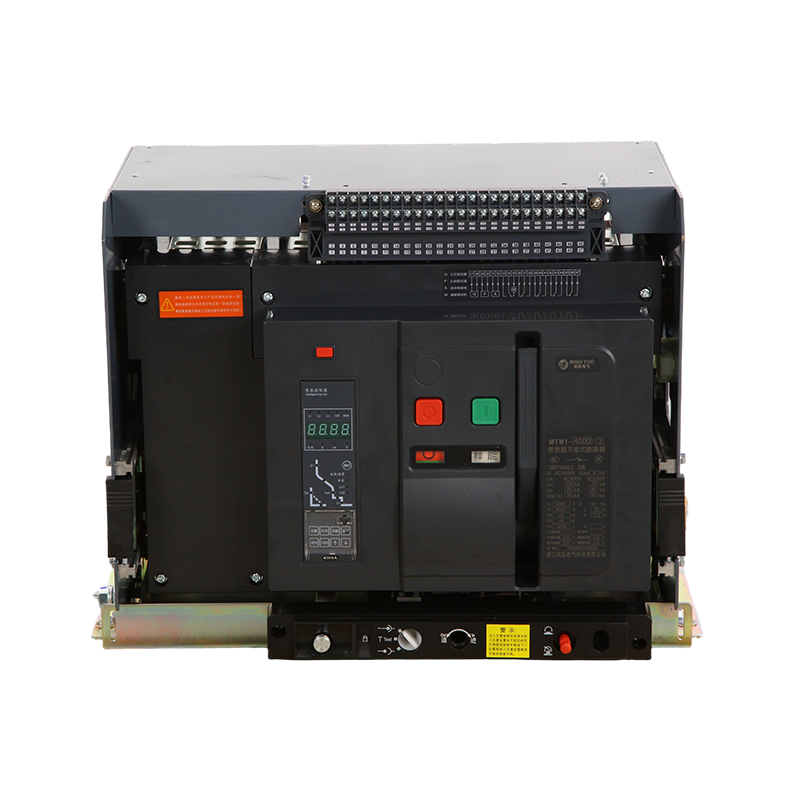
An air circuit breaker (ACB) is a switching and protection device used in low-voltage power distribution systems — typically for circuits operating at voltages up to 1,000V AC and at current ratings from 630A to 6,300A or higher. The defining characteristic of an ACB, as its name implies, is that it uses air at atmospheric pressure as the arc-quenching medium. When the breaker opens under fault conditions, the arc that forms between the separating contacts is drawn into an arc chute — a series of metallic splitter plates that divide and cool the arc, rapidly increasing its resistance until it extinguishes. This arc-quenching mechanism requires no insulating oil, vacuum interrupters, or compressed gas, making ACBs simpler to maintain and inspect than many alternative technologies.
Inside an ACB, the operating mechanism stores mechanical energy in a set of closing springs that are either manually charged or motor-charged. When a trip signal is received — from the electronic trip unit detecting an overload, short circuit, earth fault, or other protection function — a latch releases the stored spring energy and the main contacts separate at high speed. The speed of contact separation is critical: the faster the contacts open, the shorter the arcing time and the less energy is deposited into the arc chute and surrounding components. Modern ACBs achieve contact separation in under 10 milliseconds from trip signal to contact parting, and total clearing times (including arc extinction) typically under 25–40 milliseconds for short-circuit faults.
ACBs are installed at the highest current levels within low-voltage power distribution hierarchies — the main incoming circuit breakers in main distribution boards (MDBs), the primary feeders to large sub-distribution boards, and the incomer and bus coupler positions in low-voltage switchgear assemblies. Their high current ratings, robust arc-quenching capability, and extensive protection functions make them the standard choice wherever the consequences of a fault — thermal damage, fire risk, equipment destruction, or personnel safety — demand the highest level of protection and selectivity.
Typical installation environments include industrial manufacturing plants, commercial high-rise buildings, data centres, hospitals, power stations, substations, water treatment facilities, and marine electrical systems. In each of these environments, the ACB serves as the gatekeeper between the transformer secondary and the downstream distribution network, and its correct operation during a fault is the most important single event in limiting the extent and duration of an electrical incident.
Fixed ACBs are bolted directly into the switchgear panel or distribution board and cannot be withdrawn without disconnecting the busbars and cables. This design is more compact and lower in cost than drawout equivalents but requires the circuit to be de-energised and the panel to be opened for any maintenance, testing, or replacement of the breaker. Fixed ACBs are appropriate in installations where the circuit can be taken out of service for maintenance without unacceptable impact on continuity of supply — smaller industrial installations, secondary distribution boards, or systems with adequate maintenance scheduling flexibility.
Drawout ACBs are mounted on a cradle mechanism that allows the breaker to be withdrawn from the switchgear panel into a test or disconnected position without disturbing the main busbars or cable connections. In the connected position, the breaker's primary and secondary disconnecting contacts engage with fixed contacts in the panel; withdrawing the breaker to the test position isolates the main power contacts while retaining the control and auxiliary circuit connections, allowing the trip unit and protection functions to be tested under simulated fault conditions with the panel live. Full withdrawal into the disconnected position isolates all connections, allowing the breaker to be removed for maintenance or replacement while the rest of the distribution board remains energised. This capability makes drawout ACBs the standard specification for critical applications where continuity of supply to other circuits during maintenance is a requirement — hospitals, data centres, and continuously operating industrial processes.
Both fixed and drawout ACBs can be specified with motor-operated mechanisms that allow remote electrical closing and opening of the breaker without manual intervention at the panel. A motorised ACB can be controlled from a building management system (BMS), a SCADA platform, or a dedicated power management relay, enabling load management schemes, automatic transfer between supply sources, and remote fault clearance and reclosure without dispatching an electrician to the panel location. The motor spring-charging mechanism also ensures the closing springs are always recharged immediately after a close operation, making the breaker ready for rapid reclosure without manual spring charging.
Selecting an ACB for a specific application requires understanding the key ratings specified on the breaker nameplate and in the manufacturer's technical datasheet. Misapplication of these ratings is one of the most common causes of ACB failure during fault conditions.
| Rating | Symbol | Definition | Typical Range |
| Rated current | In | Maximum continuous current at rated temperature | 630A – 6,300A |
| Rated ultimate breaking capacity | Icu | Maximum fault current the breaker can interrupt once | 42kA – 150kA |
| Rated service breaking capacity | Ics | Fault current after which breaker remains serviceable | Typically 75–100% of Icu |
| Rated short-time withstand current | Icw | Fault current the breaker can carry for 1 second without tripping | 42kA – 100kA for 1s |
| Rated making capacity | Icm | Peak fault current the breaker can close onto safely | 2.1 × Icu (peak) |
| Rated voltage | Ue | Maximum system voltage for which the breaker is rated | Up to 1,000V AC |
The short-time withstand current rating (Icw) is particularly important in ACB applications and represents a capability not present in moulded case circuit breakers (MCCBs) below a certain rating. Icw allows the ACB to remain closed and carry a fault current for a defined period — typically 1 second — without tripping. This capability is essential for achieving selectivity (discrimination) in a distribution system: the upstream ACB holds closed while a downstream breaker clears the fault, limiting the extent of the supply interruption to the faulted circuit only rather than causing an upstream trip that would de-energise a wider section of the installation.
The electronic trip unit (ETU) — also called the electronic release or intelligent trip unit — is the microprocessor-based control module that monitors the current through each pole of the ACB and executes trip commands when defined protection thresholds are exceeded. Modern ETUs replace the earlier thermal-magnetic trip mechanisms with fully adjustable, precisely characterised protection functions that can be configured to match the specific requirements of each installation without replacing any hardware components.
The long-time delay function protects cables and equipment against sustained overload currents that, while below the short-circuit level, will cause thermal damage if allowed to persist. The pickup current (Ir) is adjustable, typically from 40% to 100% of the breaker's rated current, allowing the protection threshold to be matched to the actual cable ampacity rather than defaulting to the maximum breaker rating. The time delay (tr) is also adjustable, characterised by an inverse time characteristic that allows short-duration overload currents (such as motor starting inrush) to pass without tripping while protecting against sustained overloads.
The short-time delay (STD) function detects high-level fault currents and trips the breaker after a deliberate time delay — adjustable from 0.05 to 0.4 seconds in most ETUs — to allow downstream protective devices to operate first (selectivity). The instantaneous function (I) trips the breaker with no intentional delay when the fault current exceeds a very high threshold — typically set at 10–15 times rated current — representing a close-in fault where the damage potential is so severe that no delay is acceptable. The combination of adjustable STD and instantaneous settings allows the protection engineer to tailor the breaker's response curve to achieve both selectivity with downstream devices and fast clearing of severe faults.
Earth fault protection (EFP) detects residual current flowing in the earth conductor — current that has left the phase conductors but not returned through the neutral, indicating it is flowing through an unintended earth path. In TN-S and TT earthing systems, earth fault protection in the ACB provides a backup level of protection for high-impedance earth faults that might not generate sufficient current to operate the short-circuit protection. The earth fault pickup threshold (Ig) is independently adjustable, and the time delay (tg) can be set to coordinate with downstream residual current devices (RCDs).
The boundary between air circuit breakers and moulded case circuit breakers (MCCBs) is frequently misunderstood. Both technologies provide overcurrent and short-circuit protection, but they differ substantially in current rating range, breaking capacity, protection adjustability, maintainability, and cost. Understanding these differences prevents both under-specification (using an MCCB in a position that requires ACB capability) and over-specification (selecting an ACB where an MCCB would perform equally well at lower cost).
Specifying an ACB correctly requires a defined sequence of calculations and decisions that must be completed before a product can be selected from a manufacturer's catalogue. Skipping steps in this process leads to misapplication, with consequences ranging from nuisance tripping to failure to interrupt a fault safely.
Begin by establishing the rated current (In) requirement based on the maximum continuous load current of the circuit, applying any applicable derating factors for ambient temperature and installation method. Calculate the prospective short-circuit current (PSCC) at the point of installation using the transformer impedance, cable impedance, and system fault level data — this figure must not exceed the ACB's Icu rating, and ideally the Ics rating for routine serviceability after fault clearing. Determine whether selectivity with downstream devices requires an Icw rating, and if so, what time delay and current level must be achieved. Establish the ETU protection requirements — which protection functions are needed, at what settings — and confirm these are available in the selected trip unit variant. Finally, confirm the mechanical requirements: fixed or drawout, motorised or manual, auxiliary contacts and signalling outputs required for integration with the BMS or SCADA system, and busbar connection orientation compatible with the switchgear assembly.
Leading ACB manufacturers including ABB, Schneider Electric, Siemens, Eaton, and Chint publish detailed selection software and coordination tools that automate the selectivity and discrimination calculations once the system fault level and device ratings are entered. Using these tools during the design stage, rather than relying on rule-of-thumb estimates, is the most reliable way to ensure that the protection system performs as intended under actual fault conditions — which is, ultimately, the only performance that matters when a fault occurs.


Zhejiang Mingtuo Electrical Technology Co., Ltd. All Rights Reserved.
Electrical Protection Circuit Breakers Medium Voltage Circuit Breakers Manufacturers Low Voltage Circuit Breakers Factory
