 English
 Français
 Español
 عربى
عربىIndustry News
Home / News / Industry News / A Comprehensive Guide to Molded Case Circuit Breakers: Features, Uses, and Benefits

Content
Molded case circuit breakers represent a critical component in modern electrical distribution systems, providing reliable overcurrent and short-circuit protection for commercial, industrial, and residential applications. These robust protective devices combine advanced trip mechanisms with durable molded housings to deliver consistent performance across a wide range of electrical loads and environmental conditions. Understanding the features, operational principles, and proper application of molded case circuit breakers enables electrical professionals, facility managers, and building owners to make informed decisions about electrical system protection while ensuring safety, reliability, and regulatory compliance. This comprehensive guide explores the essential aspects of MCCBs, from their fundamental construction and operating characteristics through practical selection criteria and installation considerations that determine successful implementation in diverse electrical environments.
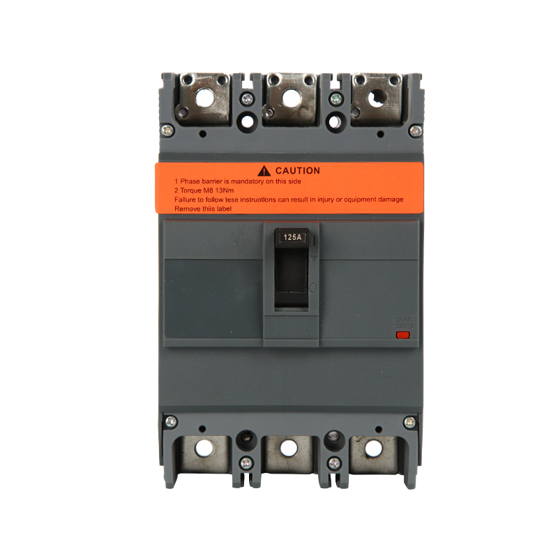
Molded case circuit breakers derive their name from the insulated molded plastic or composite housing that encases the internal operating mechanisms, contact assemblies, and trip units. This integrated design approach distinguishes MCCBs from air circuit breakers with exposed components or miniature circuit breakers with simpler construction. The molded case provides mechanical protection for internal components while offering electrical insulation between current-carrying parts and external surfaces, enabling safe handling and installation without special enclosures or barriers in most applications.
The internal architecture of an MCCB consists of several critical components working in coordination to detect fault conditions and interrupt current flow when necessary. The contact assembly includes fixed and movable contacts made from copper or silver alloys designed to carry rated currents continuously while withstanding the thermal and mechanical stresses of repeated switching operations. The operating mechanism stores energy through springs or other mechanical means, enabling rapid contact separation when the trip unit signals a fault condition. Arc chutes positioned near the contacts contain and extinguish the electrical arc formed when contacts separate under load, preventing arc propagation that could damage the breaker or surrounding equipment.
Trip units within MCCBs monitor current flow and initiate breaker operation when predetermined thresholds are exceeded. Thermal-magnetic trip units, the most common type, combine a bimetallic element for overload protection with an electromagnetic coil for short-circuit protection. The bimetallic element heats and deflects proportionally to current magnitude and duration, eventually triggering the trip mechanism when sustained overload conditions occur. The electromagnetic coil generates magnetic force proportional to current, instantly triggering trip action when short-circuit currents flow through the breaker. This dual-element approach provides coordinated protection against both gradual overloads and sudden fault conditions with response characteristics optimized for each scenario.
Electronic trip units represent an advanced alternative offering enhanced functionality and precision compared to thermal-magnetic designs. These solid-state units employ current transformers to monitor circuit current, processing the signals through microprocessor-based algorithms that determine whether trip conditions exist. Electronic trip units enable adjustable trip settings, multiple protection functions including ground fault protection, and communication capabilities for integration with building management systems. While more expensive than thermal-magnetic units, electronic trip breakers provide flexibility and features justifying their cost in applications requiring precise protection coordination or remote monitoring capabilities.
Understanding MCCB ratings and specifications proves essential for proper selection and application in electrical systems. The continuous current rating indicates the maximum current the breaker can carry indefinitely at specified ambient temperatures without exceeding thermal limits or nuisance tripping. Standard frame sizes include common ratings from 15 amperes through 2500 amperes, with each frame size accommodating multiple trip unit ratings through interchangeable or adjustable components. Selecting appropriate current ratings requires calculating maximum expected load current including reasonable growth allowances while avoiding oversizing that compromises overload protection or undersizing that causes operational disruptions.
Breaking capacity, also called interrupting capacity or interrupting rating, specifies the maximum short-circuit current the MCCB can safely interrupt without damage to the device or surrounding equipment. This critical specification must equal or exceed the available fault current at the installation point, determined through fault current calculations considering transformer capacity, conductor impedance, and system configuration. Breaking capacities for MCCBs typically range from 10kA to 200kA depending on frame size and design, with industrial-grade units offering higher ratings for applications with substantial available fault current. Installing breakers with inadequate breaking capacity creates serious safety hazards, as the device may fail catastrophically when attempting to interrupt fault currents exceeding its rated capability.
Voltage ratings indicate the maximum circuit voltage at which the breaker operates safely and maintains its interrupting capability. Standard voltage ratings include 240VAC, 480VAC, and 600VAC for alternating current applications, with some units rated for DC service at appropriate voltage levels. The voltage rating must equal or exceed the system voltage at the installation location, as applying breakers at voltages exceeding their rating compromises arc interruption capability and dielectric strength. Multi-pole breakers require consideration of both phase-to-phase and phase-to-ground voltages when verifying rating adequacy for specific system configurations.
| Frame Size | Typical Current Range | Breaking Capacity Range | Common Applications |
| Small Frame | 15-125A | 10-65kA | Branch circuits, small feeders |
| Medium Frame | 125-400A | 25-100kA | Feeders, distribution panels |
| Large Frame | 400-1200A | 35-150kA | Main distribution, large feeders |
| Extra Large Frame | 1200-2500A | 50-200kA | Service entrances, primary distribution |
Molded case circuit breakers serve diverse roles across electrical distribution systems, from service entrance equipment through branch circuit protection in commercial, industrial, and heavy residential applications. Their robust construction and wide range of available ratings make MCCBs suitable for demanding environments where miniature circuit breakers lack sufficient capacity or where air circuit breakers would prove unnecessarily expensive or oversized. Understanding typical application scenarios guides appropriate selection and ensures optimal protection coordination within overall electrical systems.
Main distribution panels in commercial and industrial facilities commonly employ large-frame MCCBs as main disconnect and protection devices, controlling and protecting entire building electrical systems or major facility sections. These main breakers typically feature high current ratings from 400 to 2500 amperes with breaking capacities suited to available fault current at the service entrance. Electronic trip units often equip main breakers to provide adjustable settings, ground fault protection, and monitoring capabilities supporting facility management objectives. The main MCCB serves as the primary safety disconnect, enabling complete de-energization of downstream systems for maintenance while protecting service entrance equipment and transformers from fault conditions originating within the facility.
Feeder protection represents another primary MCCB application, with medium and large frame breakers protecting cables or bus bars distributing power from main panels to sub-panels serving specific building areas or equipment groups. Feeder MCCBs must coordinate with both upstream main breakers and downstream branch circuit protection, requiring careful selection of trip characteristics ensuring faults clear at the lowest protective device level without unnecessary operation of upstream breakers. Proper feeder protection prevents fault propagation while maintaining service continuity to unaffected circuits through selective coordination of protective device settings.
Motor control applications utilize MCCBs for both circuit protection and manual disconnect functions in motor control centers and individual motor starters. The breaker protects cables and control equipment from short circuits while providing a visible disconnect means for maintenance safety. Motor protection MCCBs may incorporate magnetic-only trip units allowing external overload relays to provide motor-specific thermal protection, or adjustable electronic units configured for motor starting characteristics. The breaker's breaking capacity must accommodate motor contribution to fault current when multiple motors operate on a common bus, requiring higher ratings than simple load current would suggest.
Generator and alternative energy applications increasingly rely on MCCBs for protection and switching of generation equipment including emergency generators, solar inverters, and energy storage systems. These applications often require special breaker configurations handling bidirectional power flow or providing specific protection functions like reverse power detection. MCCBs in generator applications must withstand the unique stresses of connecting and disconnecting generation sources to utility grids or facility loads, including momentary paralleling during transfer operations and fault current contribution from generation equipment during system faults.
Molded case circuit breakers offer distinct advantages compared to alternative overcurrent protective devices including miniature circuit breakers, fuses, and air circuit breakers. Understanding these benefits guides appropriate application selection where MCCB characteristics provide optimal value for specific protection requirements and operational priorities.
The adjustability of many MCCB trip units enables precise matching of protection characteristics to specific load requirements without changing the physical breaker. Thermal-magnetic breakers often provide adjustable magnetic trip settings allowing optimization for different load types and fault current levels. Electronic trip units extend this flexibility dramatically, offering adjustable long-time, short-time, instantaneous, and ground fault settings that can be field-configured or modified as system conditions change. This adjustability proves particularly valuable in applications with evolving loads or where protection coordination requires fine-tuning beyond what fixed-setting devices provide, reducing inventory requirements and simplifying system modifications.
Compared to fuses providing similar overcurrent protection, MCCBs offer the significant advantage of reusability after fault interruption. Once an MCCB trips due to overload or short circuit, simply resetting the breaker after addressing the fault condition restores protection without replacement components or service interruption beyond the troubleshooting period. Fuses require replacement after operation, creating ongoing maintenance costs and requiring spare fuse inventory for rapid restoration. The reset capability of MCCBs also enables troubleshooting intermittent problems without continuous component replacement, facilitating root cause identification in complex electrical systems.
MCCBs provide superior short-circuit protection compared to miniature circuit breakers in high-fault-current applications, with breaking capacities reaching levels impractical for MCB construction. When available fault currents exceed typical MCB ratings of 6kA to 35kA, MCCBs with 50kA to 200kA ratings provide necessary protection without resorting to expensive air circuit breakers. This intermediate breaking capacity fills a critical gap in electrical system protection, enabling cost-effective solutions for industrial facilities, large commercial buildings, and other applications with substantial available fault current resulting from high-capacity transformers or proximity to utility substations.
Durability and mechanical life give MCCBs advantages in applications requiring frequent switching operations or operation in harsh environmental conditions. The robust construction with reinforced housings and heavy-duty contact assemblies enables MCCBs to withstand mechanical abuse, temperature extremes, moisture, and contaminants better than miniature circuit breakers designed for protected indoor environments. Industrial-grade MCCBs may feature sealed or gasketed housings preventing dust and moisture intrusion, along with impact-resistant cases protecting against physical damage in demanding applications. Mechanical life ratings often exceed 10,000 operations for quality MCCBs, supporting applications where breakers regularly switch loads rather than serving purely as protective devices.
Proper MCCB selection requires systematic evaluation of multiple factors ensuring the chosen device provides adequate protection while remaining compatible with system characteristics and installation constraints. Following established selection procedures prevents common mistakes that compromise protection effectiveness or create nuisance tripping conditions disrupting operations.
Load calculation forms the foundation of MCCB sizing, requiring accurate determination of maximum expected current including diversity factors for multiple loads and allowances for future expansion. For motor loads, calculate full-load current plus starting current to verify the breaker accommodates inrush conditions without nuisance tripping. Continuous loads require breakers rated at 125% of the calculated load current per electrical code requirements, ensuring the device operates within its thermal capacity indefinitely. Document all load calculations and assumptions, creating records supporting system design decisions and facilitating future modifications or troubleshooting efforts.
Fault current analysis determines the required breaking capacity by calculating maximum available short-circuit current at the breaker location. This analysis considers utility fault contribution, transformer impedance, and conductor impedance from the source to the breaker installation point. Professional calculation software or simplified methods published in electrical codes provide means for determining fault current, with conservative assumptions when precise system data remains unavailable. Always select breakers with interrupting ratings exceeding calculated fault current with reasonable safety margin, as fault currents may increase with utility system upgrades or facility modifications that weren't anticipated during initial design.
Coordination studies ensure selected MCCBs operate selectively with upstream and downstream protective devices, clearing faults at the lowest level without unnecessary operation of higher-level breakers. Plot time-current characteristic curves for all series-connected protective devices, verifying adequate separation between curves across the full range of possible fault currents. Electronic trip breakers with adjustable settings enable fine-tuning coordination that may prove impossible with fixed thermal-magnetic devices. Coordination becomes particularly critical in systems where unnecessary upstream breaker operation creates extensive outages affecting large facility areas or critical processes requiring continuous operation.
Proper installation and ongoing maintenance ensure MCCBs deliver reliable protection throughout their service life, typically 20-30 years for quality devices in appropriate applications. Following manufacturer guidelines and industry best practices prevents premature failures while maintaining protection effectiveness and safety characteristics essential for electrical system integrity.
Mounting orientation and clearance requirements must be observed to ensure proper breaker operation and heat dissipation. Most MCCBs are designed for vertical mounting with specific top-bottom orientation indicated on the device or in documentation. Incorrect mounting may affect trip calibration, particularly for thermal-magnetic units where gravity influences bimetallic element operation. Maintain manufacturer-specified clearances above, below, and beside breakers to enable adequate cooling air circulation, preventing elevated temperatures that accelerate insulation aging or alter trip characteristics. Crowded panel installations limiting air circulation may require derating breaker current capacity to prevent thermal problems.
Torque specifications for terminal connections critically impact both electrical performance and mechanical reliability, requiring adherence to manufacturer-published values during installation and maintenance. Under-torqued connections create high resistance joints generating excessive heat that damages terminals and conductors while potentially causing connection failure. Over-torquing damages terminal threads, deforms bus bars or lugs, and may crack insulating components surrounding terminals. Use calibrated torque tools and verify all connections meet specified values, documenting torque verification as part of installation records. Re-torque connections during commissioning and periodic maintenance as thermal cycling can loosen fasteners over time.
Periodic testing and maintenance preserve MCCB protection capabilities throughout the device service life, with testing frequency based on application criticality and operating environment. Visual inspection during annual maintenance identifies obvious problems including damaged housings, corrosion, loose connections, or signs of overheating. Functional testing verifies manual operation smoothness and contact continuity, while trip testing using specialized equipment confirms protection settings remain within acceptable tolerances. Electronic trip breakers may incorporate self-test features providing continuous monitoring of trip unit functionality, reducing testing burden while improving protection reliability through early fault detection.
Molded case circuit breakers represent sophisticated protective devices combining robust mechanical construction with precise overcurrent detection and interruption capabilities essential for modern electrical distribution systems. Their versatility across diverse applications from branch circuits through main service entrances, combined with advantages in adjustability, breaking capacity, and durability, establishes MCCBs as indispensable components in commercial and industrial electrical infrastructure. Proper selection considering load characteristics, fault current, coordination requirements, and environmental factors ensures optimal protection while avoiding common pitfalls that compromise safety or create operational disruptions. Through understanding MCCB features, applications, and benefits, electrical professionals can specify and maintain these critical devices confidently, supporting safe, reliable electrical distribution systems serving our increasingly electrified world.


Zhejiang Mingtuo Electrical Technology Co., Ltd. All Rights Reserved.
Electrical Protection Circuit Breakers Medium Voltage Circuit Breakers Manufacturers Low Voltage Circuit Breakers Factory
