 English
 Français
 Español
 عربى
Industry News
Home / News / Industry News / MCB Circuit Breaker Symbols: How to Read Them Correctly in Electrical Drawings


Content
When you open an electrical drawing, a miniature circuit breaker (MCB) is represented by a simple rectangle with a diagonal line. Yet that rectangle can hide a lot of information. The same basic shape may mean a single-pole breaker for a lighting circuit, a three-pole breaker for a motor, or a breaker with a different trip characteristic. The good news is that once you know how to read the symbol correctly, you can quickly identify what the breaker is, what it protects, and how it should be wired.
The standard MCB symbol is based on an ordinary switch symbol. It shows a moving contact that can open or close the circuit. The difference is that a standard circuit breaker adds protection elements on top of the switch function. In IEC 60617, the thermal-magnetic function is drawn as a small half-square and a small half-circle attached to the contact arm. The thermal element, often written as a square wave, represents overload protection. The magnetic element, often drawn as a half-circle, represents short-circuit protection.
This is why you will sometimes see an MCB symbol with a curly or stepped line next to the switch. That little mark is not decoration. It tells an installer that the device has a thermal release for overload and a magnetic release for short circuit. If the symbol only shows a straight switch with a small loop, it might be a switch disconnector, not a breaker.
There are two common ways to draw a circuit breaker symbol. The IEC 60617 symbol is widely used in Europe, Asia, and many international projects. The ANSI/IEEE 315 symbol is common in North America. Both convey the same function but look different on paper.
| Feature | IEC 60617 | ANSI/IEEE 315 |
|---|---|---|
| Basic breaker | Line with a small angled gap | Line with a filled semicircle in the gap |
| Thermal trip | Small square wave | Small curved loop or letter |
| Magnetic trip | Small half-circle | Slash or an X shape |
| Multi-pole linkage | Dashed line between contacts | Dashed line or hatched line |
The table shows the basic visual differences. For an engineer, the key point is to check the project standard before you start reading the drawing. If you mix IEC and ANSI on the same schematic, a person may misinterpret a breaker as an isolator or the other way around.
Pole count is the first thing to confirm. A single-pole (1P) MCB symbol shows one contact line. A two-pole (2P) symbol shows two contact lines connected with a dashed vertical line. A three-pole (3P) symbol shows three lines, and a four-pole (4P) symbol shows four. The dashed line means the poles operate together, so when one trips, all poles open at the same time.
The pole count matters when you select hardware for a panel. A 3P breaker cannot be used where a 4P is needed, and using a 4P where a 2P is sufficient increases cost and cabinet space.
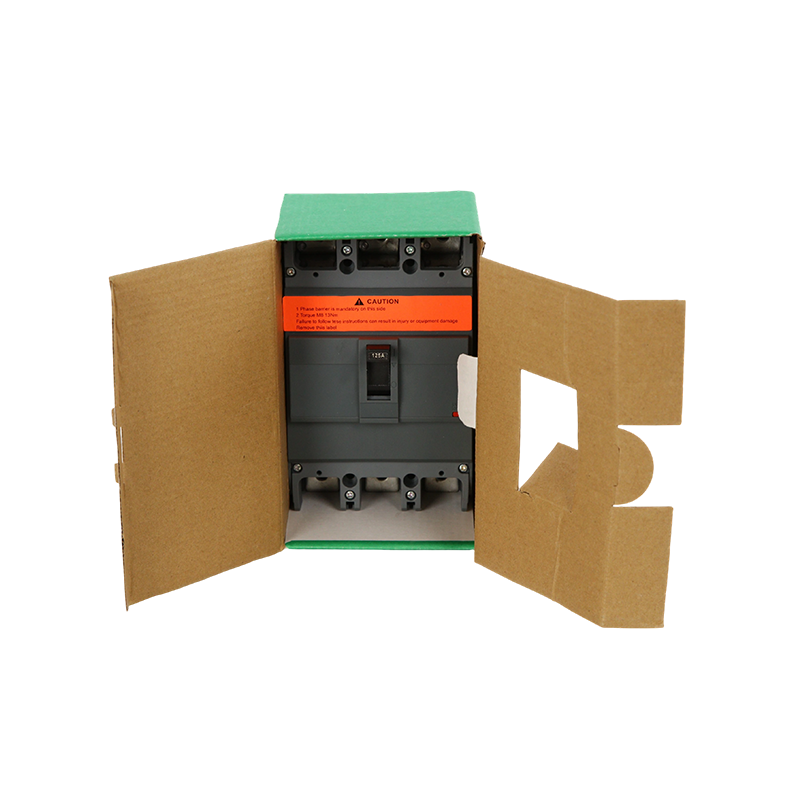 EZC Molded Case Circuit Breaker 100A–630A for Low-Voltage DistributionThis breaker suits main incoming and feeder protection in industrial and commercial networks, offering thermal-magnetic response for overload and short-circuit conditions. Its current range supports various distribution tasks while considering pole count and cabinet space.View Product →
The miniature circuit breaker symbol and the moulded case circuit breaker (MCCB) symbol are similar but not identical. Both show a switch with thermal-magnetic protection. The main difference is that an MCCB symbol often has a larger trip frame or a heavier line weight because it is designed for higher current ratings. On a single-line diagram, an MCCB may be drawn with a thicker line to indicate a larger frame size.
In practice, you should not rely on the symbol alone to know the rating. The symbol tells you the function and the number of poles; the rating is always printed on the schedule or on the product itself. When you are selecting a device for a specific load, you need to compare the actual current rating, breaking capacity, and trip curve against the project requirements.
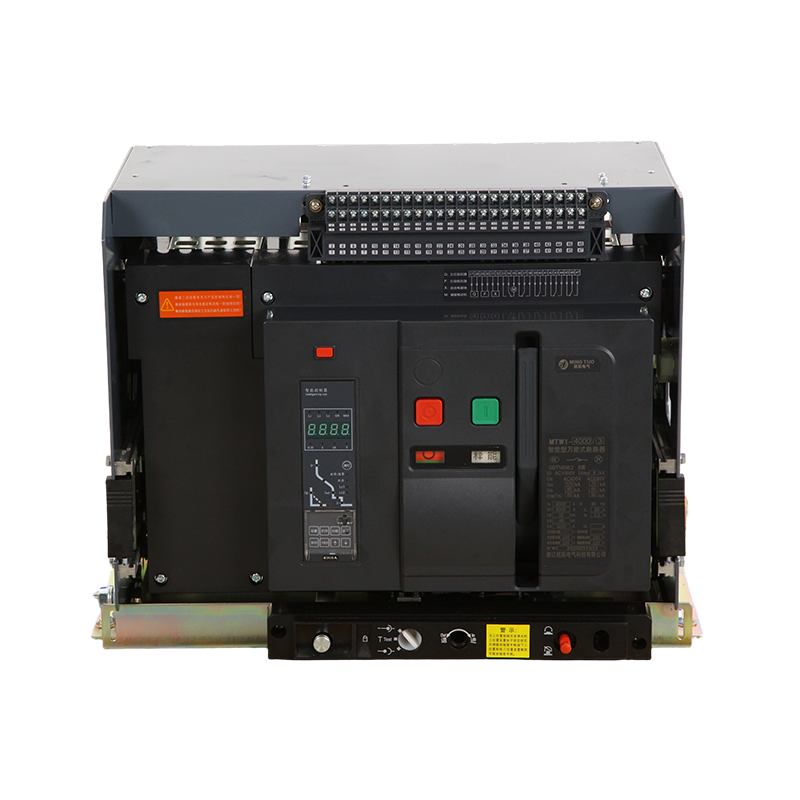
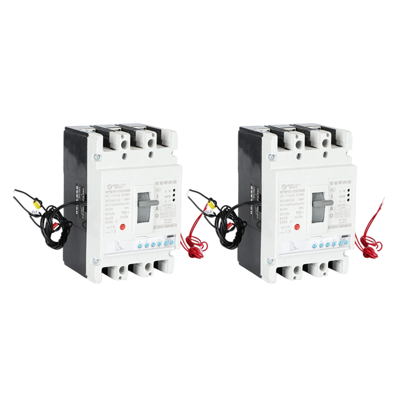 MT-M1 Digital Electronic MCCB 100-800A, 3/4P, 50kAWith microprocessor control, this breaker provides programmable protection and real-time monitoring for overload, short-circuit, and ground faults. Ideal for systems requiring precise settings and data-driven energy management, complementing symbol-based understanding of ratings.View Product →
When you look at a single-line diagram, the breaker symbol is usually placed on a vertical or horizontal line. The steps to read it are straightforward:
These steps take a few seconds, but they prevent errors in panel layout and wiring.
One of the most common mistakes in reading breaker symbols is confusing a switch-disconnector symbol with a breaker symbol. The switch-disconnector has no thermal or magnetic trip marks. Another mistake is misreading a 2P symbol as 1P+N. In some standards, 1P+N is drawn with one line for the phase and a thinner line for the neutral, while a true 2P breaker has two equal lines with a dashed linkage. This difference has real consequences: a 1P+N breaker does not sense overcurrent on the neutral, while a 2P breaker may or may not include neutral protection depending on the design.
You also need to consider the application before choosing the hardware. For a photovoltaic array, for example, a DC-rated breaker is required because AC ratings cannot guarantee the same interruption performance in DC circuits. A broader guide to LV and MV protection can help you match the device to the system.
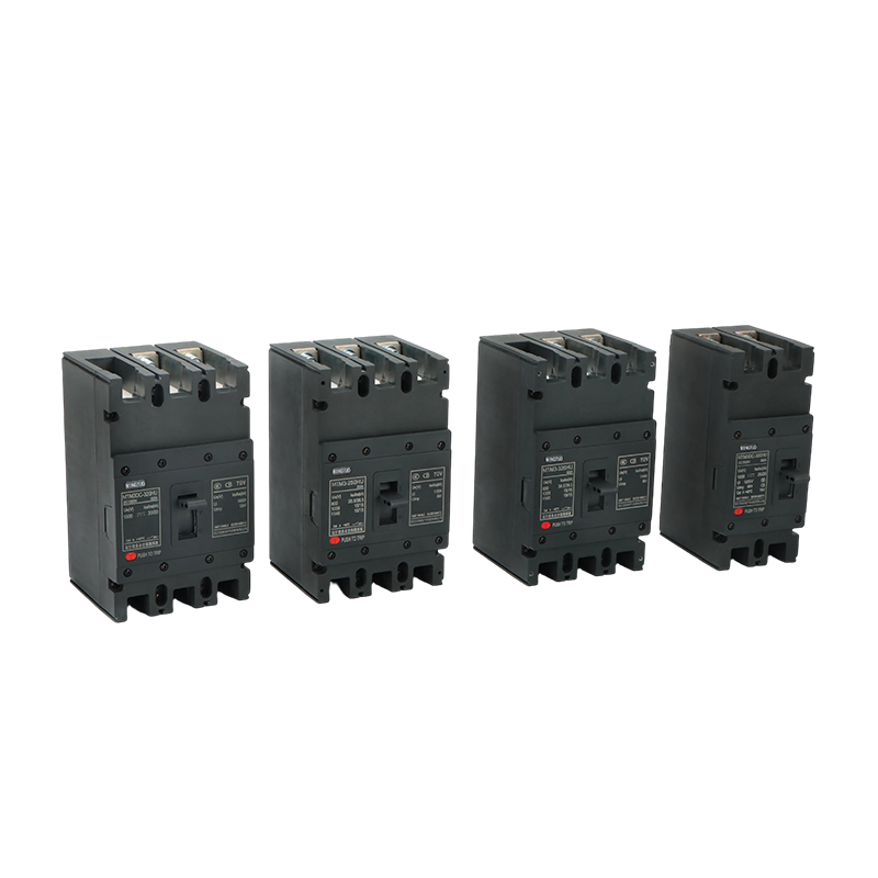 PV DC MCCB 1000V 630A for Solar Photovoltaic ProtectionDesigned for photovoltaic arrays, this DC-rated breaker ensures safe interruption in solar combiner boxes, inverter protection, and storage systems. Its voltage and current ratings address the DC application needs highlighted in the surrounding discussion.View Product →
Learning the MCB circuit breaker symbol is a small but important skill for anyone who works with electrical drawings. It helps you avoid wrong panel designs, reduce installation errors, and communicate more effectively with engineers and electricians. If you are looking for a supplier that understands both symbols and real-world application, our company profile explains how a technical manufacturing team can support your project. The right device starts with the right reading.
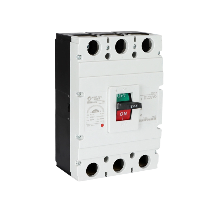

Zhejiang Mingtuo Electrical Technology Co., Ltd. All Rights Reserved.
Electrical Protection Circuit Breakers Medium Voltage Circuit Breakers Manufacturers Low Voltage Circuit Breakers Factory
